Letter From the Director

Thoughts From My Desk…

“You are simply not going to believe it.” This is the phrase I have been using regularly as I talk with many of you reading this magazine, whether you are a CFA member, or one of the many companies across this great country to whom I have the privilege of casting our voice. Where I use this phrase is in the promotion of the one thing CFA is known for more than anything else: our networking.
Listen, I am involved on a daily basis – yes, daily – in resolving conflict in our industry. Often I am fielding a question by a member challenged by an inspector, gathering information to share in defense of a company’s decision to meet an OSHA regulation, or responding to a claim that a company has installed concrete improperly. All of these chances I get to be an advocate for the concrete industry, however, pale in comparison to the impact I see and hear when I am in the same room as company representatives just like you. Yes, you, the one reading this letter… Picture my finger pointing at you.
From “I’m simply too busy” to “We don’t have enough coverage right now,” to “We’re not quite ready to join” – there must be a thousand reasons why more than 5,000 companies receive this magazine but do not do anything more with it. That is not stated to single you out, for you are not alone. In fact, you are in the majority. The majority of companies in this industry, or in any industry, for that matter, will never take the inspired step or the calculated risk to invest in themselves and open up their collective minds to see a much broader picture of potential. And then, there are the 300 or so that do. What does it look like on the inside? That is where my phrase comes in: “You are simply not going to believe it.”
I sat in a meeting two weeks ago in Philadelphia, the same meeting that our president, Phil Marone, was at. In this meeting, only two people knew each other (outside of me as the host, and our education consultant and mentor, Rocky Geans). These happen to be the two companies local to the event. The remainder of the room had never met. When it was all said and done, they could not wait to get back together, as they had begun the formation process to become a Management Exchange Networking group. That doesn’t make things easier; it rewards the harder. The more you expose yourself, opening yourself up to others’ ideas, the more rewarding your future will be. I heard one company describe the challenges they faced in creating their schedules, another in keeping control of workers’ compensation insurance, and another trying to figure out who would call in sick and who would respond to the rescheduling of their work. These were all shared within the group, and everyone had a strategy to share or a corroborating experience; and, as a group, they came to even larger decisions.
You are simply not going to get any better by being the same company tomorrow as you are today. You are not going to open your doors to the competition that is around you, letting it come in and look at your business or listen to your struggles. You are not going to win any battles with customers, inspectors or compliance officers by presenting the same responses you gave last time. The only way to move forward in this industry, or in any industry for that matter, is to stop and consider yourself a leader. Good leaders do not merely follow, and they do not demand. What a good and successful leader will do is make the informed decision to invest in their company by becoming affiliated with like-minded leaders. Then those companies can serve each other by getting in the room, listening and sharing. What do I want for your 2018 Christmas? I absolutely want peace and joy for you, but I also want success – success you are simply not going to believe until you experience it. Become a member!

Letter from the President

Hello CFA Contractor and Associate Members!
With the close of 2018 almost here, I view this as the perfect time to offer some thoughts regarding our businesses and our association.
It seems that each year brings new challenges and that running our businesses takes more of our time and energy. Even in a good economy, we are constantly tested and confronted with decisions to keep us in the black. Increasing regulations, lawsuits, labor shortages, workers’ compensation, material prices and insurances make it complicated to remain profitable. The advancement of technology has made it important to change the ways we do business even more quickly. The five-year plan of the past seems to run its course much more quickly.
All that stated, it is important to look at how we do business more frequently and find ways to improve our processes and procedures to stay on top of a rapidly changing environment.
Our organization is one of the best resources for staying relevant and on top of your game. We have resources, education, and like-member companies to associate with and help keep your businesses fresh! Being a member is one thing, but being an involved member is where the rubber meets the road. As is often said, you can only get out of something what you put into it.
In November, our CFA brought the Rocky Geans Construction School to Philadelphia, along with the opportunity for certification testing. Companies that realized the importance of taking advantage of the membership met for two days of education. Companies from Pittsburgh, Central Pennsylvania, Baltimore, Atlanta, New York, New Jersey and the Philadelphia metro area attended. The event not only educated the attendees, but also opened the door for dialog amongst similar companies. Additionally, the meeting provided some of the companies with an opportunity to get involved with Management Exchange Groups. Initiated several years ago, these are groups of non-competing companies that meet on their own a couple times each year to share information with each other that can further improve each others’ businesses.
The CFA business schools, certification processes, and education opportunities will be available in regional areas in the future. Engaging in these opportunities is a great way to take advantage of our organization. I am personally challenging you to set aside the traditional response that you do not have time, and to find a way to make a difference in your future!
Best wishes for the close of the year, for your families, and for happy holidays!
![]()
CONCRETE FOUNDATIONS ASSOCIATION ANNOUNCES NEW AFFINITY MEMBER BENEFIT PROGRAM
FOR IMMEDIATE RELEASE
For further information contact:
Lindsey Bloomquist
Manager of Communications and Networking
Concrete Foundations Association
Telephone: (319) 895-6940
E-mail: lbloomquist@cfaconcretepros.org
CONCRETE FOUNDATIONS ASSOCIATION ANNOUNCES NEW AFFINITY MEMBER BENEFIT PROGRAM
Mount Vernon, IA November 30, 2018 – The Concrete Foundations Association (CFA) – the recognized voice and authority for the cast-in-place concrete industry, has entered into a relationship with Business AdvantEdge, Inc., to begin saving member organizations thousands of dollars annually simply by maintaining an active CFA membership and registering for specific services.
![]()
Mary Hazzard of Business AdvantEdge states, “We do the work of negotiating with national organizations to deliver savings to individual company users through their affiliation with key organizations like the Concrete Foundations Association. In so doing, an average company using a handful of the services provided through this relationship can easily generate more than $4,000 of annual savings over independently negotiated contracts with these providers.”
Business AdvantEdge is designed to bring BIG business discounts to SMALL businesses. A member benefit driven organization, they offer small business owners and trade associations discounted business inventory and services. “We hold contracts with major supply companies that allow us to pass along savings and other value added in the form of member benefits,” states Hazzard.
“During each Board meeting, our directors discuss ways of entering into agreements with large national firms to leverage our combined buying power,” states James Baty, CFA Executive Director. “Business AdvantEdge approached us with a universal solution and a diverse directory of services we felt was an automatic step in the right direction. Not that the value of membership needed further justification but this is one of those connections that pays you for becoming a member.”
The suite of service providers offered to CFA members beginning this December includes ways to save money on:
- Fleet Fuel and Propane
- Waste and Recycling Management
- Office supplies and Technology
- MRO – Maintenance, Repair and Operations
- HR – Payroll Processing and Employee/Drug Screening
- Shipping
- Workwear and Facility Services
- Truck and Vehicle Rentals
- Telecom – Land and Mobile phone services
Examples of these advantages include Office Depot where up to $70 is saved on the first purchase by 12/10/2018 and up to 65% after that. Also, Fleet Fuel Programs by Exxon Mobil, Phillips 66, Conoco, 76, Stripes and Circle K have per gallon savings between 10 and 15 cents for the first half of 2019 and 5 to 6 cents thereafter.
To find out how you can begin benefitting from these programs or to see the complete line-up of affinity services, contact CFA Executive Director, James Baty for more information on CFA membership and this Business AdvantEdge relationship.
Keep tuned to CFA communications as we launch these terrific new member benefits. You save all year long, however for December, we have several limited time promotions that are available if you act fast! Details and enrollment instructions are found at our new CFA MarketPlace.
ABOUT CONCRETE FOUNDATIONS ASSOCIATION
The Concrete Foundations Association (CFA) is the recognized voice and authority for the residential concrete industry. Originally formed as the Poured Concrete Wall Contractors of America, Inc. (PCWCA), the CFA was formed in 1974 to serve the interests of poured wall contractors. The CFA has members throughout the U.S. and Canada as well as overseas representing all aspects of the cast-in-place industry including construction, design and manufacturing. Member firms are diverse in size and volume as well as business models with many operating across residential, agricultural and commercial markets. For more information, visit www.cfaconcretepros.org or contact CFA at 319-895-6940.
###
Concrete Foundations Association Announces New Member Benefit – Savings4Members
CONCRETE FOUNDATIONS ASSOCIATION ANNOUNCES NEW MEMBER BENEFIT SAVINGS4MEMBERS
Mount Vernon, IA November 30, 2018 – The Concrete Foundations Association (CFA) – the recognized voice and authority for the cast-in-place concrete industry, has entered into a relationship with Business AdvantEdge, Inc., to begin saving member organizations thousands of dollars annually simply by maintaining an active CFA membership and registering for specific services.
Mary Hazzard of Business AdvantEdge states, “We do the work of negotiating with national organizations to deliver savings to individual company users through their affiliation with key organizations like the Concrete Foundation Association. In so doing, an average company using a handful of the services provided through this relationship can easily generate more than $4,000 of annual savings over independently negotiated contracts with these providers.”
Business AdvantEdge is designed to bring BIG business discounts to SMALL businesses. A member benefit driven organization, they offer small business owners and trade associations discounted business inventory and services. “We hold contracts with major supply companies that allow us to pass along savings and other value added in the form of member benefits,” states Hazzard.
“During each Board meeting, our directors discuss ways of entering into agreements with large national firms to leverage our combined buying power,” states James Baty, CFA Executive Director. “Business AdvantEdge approached us with a universal solution and a diverse directory of services we felt was an automatic step in the right direction. Not that the value of membership needed further justification but this is one of those connections that pays you for becoming a member.”
The suite of service providers offered to CFA members beginning this December includes ways to save money on:
- Fleet Fuel and Propane
- Waste and Recycling Management
- Office supplies and Technology
- MRO – Maintenance, Repair and Operations
- HR – Payroll Processing and Employee/Drug Screening
- Shipping
- Workwear and Facility Services
- Truck and Vehicle Rentals
- Telecom – Land and Mobile phone services
Examples of these advantages include Office Depot where up to $70 is saved on the first purchase by 12/10/2018 and 65% on average after that. Also, Fleet Fuel Programs by Exxon Mobil, Phillips 66, Conoco, 76, Stripes and Circle K have per gallon savings between 10 and 15 cents for the first half of 2019 and 5 to 6 cents during the second half.
Keep tuned to CFA communications as we launch these terrific new member benefits. You save all year long, however for December, we have several limited time promotions that are available if you act fast! Details and enrollment instructions are found at our new CFA MarketPlace.
ABOUT CONCRETE FOUNDATIONS ASSOCIATION
The Concrete Foundations Association (CFA) is the recognized voice and authority for the residential concrete industry. Originally formed as the Poured Concrete Wall Contractors of America, Inc. (PCWCA), the CFA was formed in 1974 to serve the interests of poured wall contractors. The CFA has members throughout the U.S. and Canada as well as overseas representing all aspects of the cast-in-place industry including construction, design and manufacturing. Member firms are diverse in size and volume as well as business models with many operating across residential, agricultural and commercial markets. For more information, visit www.cfaconcretepros.org or contact CFA at 319-895-6940.
For Sale: BEP Gang-“like” Aluminum Forms
CFA member from Iowa is looking to reduce form inventory by selling a set of vertex brick textured “big” aluminum panel forms. These forms are 9-ft tall and have an inventory including:
- 8 – 6 ft (w) x 9 ft (h) [72″ x 108″]
- 8 – 9 ft (w) x 9 ft (h) [108″ x 108″]
- 8 – 12 ft (w) x 9 ft (h) [144″ x 108″]
- 8 – 15 ft (w) x 9 ft (h) [180″ x 108″]
- 6 – 18 ft (w) x 9 ft (h) [216″ x 108″]
- 4 – 21 ft (w) x 9 ft (h) [252″ x 108″]
- 8 – 18 ft (w) x 4 ft (h) [216″ x 108″]
- 8 – 6×6 inside corners
For more information regarding these forms and any transaction interest, contact David Martinson, Ph. 319.232.4000.
Custom Concrete Expands Regionally with New Addition
The Central Indiana-based company has acquired Triple Q Foundations out of the Greater Cincinnati area
WESTFIELD, Ind. (Oct. 23, 2018) — Custom Concrete, central Indiana’s quality concrete contractor, today announced it has acquired Triple Q Foundations, based in Lebanon, Ohio. The acquisition was finalized on Oct. 1, 2018.
The addition of Triple Q Foundations expands Custom Concrete’s footprint beyond central Indiana to the tri-state region of southeastern Indiana, southwestern Ohio and northern Kentucky.
Triple Q owners John and Tim Ball announced their intention to sell the company on Sept. 24, 2018.
“Triple Q Foundations shares Custom Concrete’s desire and ability to be innovative, especially when it comes to taking care of its customers and employees,” said Triple Q co-founder John Ball. “We are confident this is a good match.”
Darren Poore has been named president of Triple Q effective immediately. Poore was previously with Baker Concrete Construction for 13 years, managing numerous commercial and industrial concrete construction projects throughout the Midwest, southern United States as well as Colorado. Prior to Baker Concrete, Poore worked as the operations manager for Ball Brothers/Ball Concrete Construction focused on residential projects.
“We are excited to have Triple Q join our family,” said Custom Concrete Owner and CEO Brad Schrock. “John and Tim have created a great company and we are committed to making sure this change in ownership goes as smoothly as possible.”
Custom Concrete has been constructing foundations for the finest homes, commercial buildings and industrial facilities throughout central Indiana since 1969.
To learn more about Custom Concrete, visit http://customconcrete.com/.
Stephens & Smith Construction Company Revives Student-Learner Program
FEATURE ARTICLE:
Stephens & Smith Construction Company Revives Student-Learner Program
By Jereme Montgomery, Business Development
Many of you reading this article will testify that the skill gap is real. There is a shortage of skilled craftsmen in the construction industry, and it has continued (and will continue) to effect quantity and quality of structures built in America. I’d like to take it one step further: More important than the skill gap, is a lack of awareness regarding construction careers available. It is time the construction industry, and specifically the individual trades within it, take action. Let’s stop blaming the education system for lack of emphasis on trades. Let’s stop blaming parents for “brain-washing” youth into believing that a four-year college is the only path to success. If we truly want to see change in career awareness for construction trades, we have to become advocates at a local level. That is precisely what we are determined to do here at Stephens & Smith.
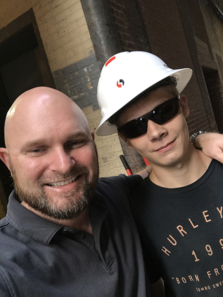
In May of 2018, leaders in the construction industry around Lincoln, Nebraska took it upon themselves to coordinate a “hands-on” construction career day. The Home Builders Association of Lincoln, in conjunction with Build Our Nebraska, worked with public and private schools to create an event dedicated to creating construction career awareness. Over twenty local construction companies and equipment suppliers sponsored multiple exhibits where youth could experience many of the activities or “jobs” associated with working in construction. These were jobs like driving skid loaders, operating backhoes, using hand tools, finishing concrete, and many other hands-on activities. It was the first construction career day organized in Lincoln for over a decade. During the event, I had the pleasure of meeting a 17-year-old student who was cleaning up from stamping some concrete. As I began a conversation, he said, “I want to do that. I want to be a concrete finisher.” Without hesitating I replied: “Say no more.” One month later, our company hired its first 17-year-old employee since the 1980s, Mr. Diamond Potter.
The U.S. Department of Labor’s Employment Standards Administration defines seventeen hazardous occupations in non-agricultural settings. According to the Fair Labor Standards Act, or the Wage-Hour Law, the safety and well-being of a young person is to be protected by employers. They may not allow minors to perform work that has been determined by the secretary of labor to be hazardous. Hazardous Occupation Orders generally prohibit youth under the age of 18 to engage in occupations and activities such as:
- Manufacturing and storing explosives
- Motor-vehicle driving and being an outside helper
- Coal mining
- Logging and saw milling
- Using power-driven woodworking machines (including saws)
- Being exposed to radioactive substances
- Operating power-driven hosting devices, including forklifts, cranes, and non-automatic elevators
- Using power-drive metal forming, punching, and shearing machines
- Mining other than coal mining
- Slaughtering or meat packing, processing or rendering, including the use of power-driven meat slicers*
- Operating power-driven bakery machines
- Using power-driven paper product machines, including paper balers*
- Manufacturing brick, tile, and similar products
- Using circular saws, band saws, and guillotine shears*
- Wreaking, demolition and ship-breaking
- Roofing operations*
- Excavating, including work in a trench as a plumber*
*Exemptions: Student-learners aged 16 or 17 enrolled in career education programs that meet the minimum requirements may be employed on a limited basis in the five hazardous occupations listed with an asterisk (*). Under these requirements, the agreement must provide that:
- The student-learner is enrolled in a course of study and training in a cooperative vocational training program.
- Student-learners employed under a written agreement must provide:
- That the work of the student-learner in the occupations declared particularly hazardous shall be incidental to his/her training;
- That such work shall be intermittent and for short periods of time, and under the direct and close supervision of a qualified and experienced person;
- That safety instructions shall be given by the school and correlated by the employer with on-the-job training; and
- That a schedule of organized and progressive work processes to be performed on the job shall have been prepared.
 Sounds like a lot, and it should. Our industry can be dangerous without proper instruction or guidance. The safety of these student-learners is priority number one. Prior to the hiring of our student learner, Stephens & Smith Construction Company worked closely with the Nebraska Department of Education and the Nebraska Department of Labor to ensure we had all our “ducks in a row.” Since I volunteered to become Mr. Potter’s concrete mentor, I have had the pleasure of reviewing his first essay of the summer required for class. I quickly realized that this student-learner’s experience was not only about teaching career awareness, but was also about teaching life lessons. To prove this, his essay required him to answer three questions:
1. What can you learn from a job that you cannot learn in a traditional classroom?
Since my summer employment, I have learned many things about my job that I wouldn’t have learned in a traditional classroom. First, you can’t pour or finish concrete in a classroom. When you’re in a classroom you don’t get to interact with other concrete tradesman. Also, I have learned how equipment helps make our jobs easier. Most importantly I have learned by doing hands-on construction activities.
2. What do you like most about your job?
What I like most about my job is simply being outside. I enjoy NOT having to sit behind a desk and I enjoy the view when working outside. I also enjoy building things. It is nice to look back at what we built for the day and say, “I helped build that.” A couple other things I enjoy most about my job is the people [sic]. They are fun to work with, even when things get tough. Lastly, I definitely enjoy the money the most. This will help me fix my car and save up for an apartment when I graduate.
3. What do you like least about your job?
Early mornings are what I like the least. I have learned that in order to “beat the heat,” we have to start before the sun comes up. Then we have work in the hot sun for the rest of the day. It is hard work. I enjoy what I do and the people I work with. I’ve learned that you have to stay busy in order to earn respect from my co-workers. Earning respect is important with any job.
– Diamond Potter, June 29, 2018
This has been a true learning experience for us at Stephens & Smith. We realize that this opportunity is unique, and we hope other construction companies take advantage of this program next summer. Mr. Potter is the first student learner in Nebraska since the late 1980s who has taken the proper legal steps to work in Nebraska’s construction industry. This is great news for our industry and a great chance to show off our trades. It is high time more construction companies take advantage of student-learner programs. Local advocacy is, and will continue to be, the most effective recruitment tool we have in our toolbox. Don’t let it get rusty. Our path is not a difficult one to follow, and if your company is a CFA member, I would love to help you with a blueprint for understanding your state requirements and setting a path toward engaging student learners for your future operations.
Jereme Montgomery is the former Director of the Nebraska Concrete & Aggregates Association. He now serves as a business development member for CFA, Stephens & Smith Construction Company Inc. is located in Omaha and Lincoln, Neb. | @NEconcrete | www.stephensandsmith.com | JMontgomery@stephensandsmith.com
Resources:
- USDOL page with useful information: https://www.dol.gov/general/topic/youthlabor/hazardousjobs.
- Regulations (Subpart E for hazardous occupations): https://www.ecfr.gov/cgi-bin/text-idx?c=ecfr&sid=48d6ee3b99d3b3a97b1bf189e1757786&rgn=div5&view=text&node=29:3.1.1.1.31&idno=29#sp29.3.570.e.
- Safety resource for Young Worker Safety and Health: https://www.cdc.gov/niosh/topics/youth/.
- USDOL website designed for youth https://www.youthrules.gov/.
Get More Workers: How to Use an Employee Referral Program to Bring in More People
By Doug Herbert
How much does it cost a contractor to hire one employee? According to my concrete contractor buddies, Sean Smith from Cleveland, Ohio and Jason Ells from Indianapolis, Indiana, the amount is at least $1,000 per new employee. Based on my experience and calculations, that number is spot on.
Here are just some of the areas where we spend time and expenses when hiring an employee:
- Writing and placing the “Help Wanted” ad
- Reviewing the applications
- Interviewing the applicants
- Having the new hire fill out the new employee paperwork
- Sending the new hire down for a drug test (if your company requires that)
- Having the new hire go through company orientation
- And, finally, training – whether formal training, or just having them pick it up from the men on the job sites
Additionally, if you do any of these tasks yourself, you have to factor in the opportunity cost: If you were not spending your time doing this, you would likely be spending your time doing something more profitable. Examples of more profitable activities include getting a new customer, implementing a new system, or getting a better price on materials. The opportunity costs really make hiring an employee an expensive proposition.
When you add in the costs of people you hire who do not contribute on the job site and only last a few days or a few weeks, the costliness of the undertaking can become downright frightening.

Reduce Hiring Costs with Employee Referrals
One of the best ways to reduce these costs is to set up an employee referral program that encourages your employees to refer their friends and peers to join your company.
Referred employees are more likely to be better employees because birds of a feather flock together. Your good employees likely know other good workers. The people that they refer are usually better workers than a random person answering your “Help Wanted” ad.
Also, the referred person will feel more obligated to come to work every day because their friend will know if they call in sick or miss a day. Or, as we have seen happen, the new employee is more likely to get to work each day due to ride sharing with the one who referred them.
How to Set Up the Program
Set up an employee referral plan at your company for your current employees. When they refer someone to your company that you hire, they get a referral bonus if that new hire stays with you for a certain period of time.
I recommend that the new employee has to be there for 90 days before the referral bonus is paid out. On their 90th day, the employee that referred them gets the referral bonus.
What will motivate your employees to refer others to join your company? The answer is, simply, money. Sure, some people are motivated by other things like time off, prizes or perks. Money, however, is the universal motivator. Everyone has a use for it. Offer a monetary bonus between $150 and $400 as your referral reward. Consult with your attorney and accountant for the best way to do this.
Concrete contractors will often balk at that dollar amount. They think it is too high, but I believe it is very inexpensive compared to hiring the wrong person. The caliber of men you will get from employee referrals will almost always be better than guys just walking in off the street, applying for a job.
You want more people like your current employees. Your current employees know what the work is like, they know what is required of them, and what the hours are like. The people that they refer are going to be similar to them.
I love this concept because there really is not much risk for the contractor. If the new employee is not a good worker, then either they will quit or you will get rid of them before 90 days.
If they are a good worker and they have been there for 90 days, then they will probably stay for a while, which is what we want. Besides, you have made more on their labor up to this point than whatever the referral bonus is.
Five Common Mistakes
There are five common mistakes I often see contractors making when they implement an employee referral strategy.
 The first mistake is making the referral bonus too small. The bonus has to be big enough so your employees persuade others to work at your company. You want your employee to think about what they would do with all of that money. Fifty bucks is not going to motivate someone. It has to be a bigger reward than that.
 The second mistake is not creating a good place to work. Employees will not refer their friends if they themselves do not enjoy working there. Be sure you provide a safe, reliable place to work, where your employees feel like they are a valuable part of a team and are appreciated.
 The third mistake contractors make with referral bonuses is that they pay some or all of the money when the referred person begins working at the company. For one thing, this is expensive. For another, we are trying to find people who will stay with the company, and will work hard enough not to get fired.
You do not want one of your employees sending you crappy people who do not last more than a week just so he or she can get the bonus. We must always reward the behavior we want repeated. So, pay the bonus to every person who refers someone who lasts more than 90 days.
 The fourth mistake I see is that contractors make the referral bonus program too complicated. They set it up so the referrer gets 50 bucks when the person starts, then both people will get 100 bucks after 60 days, then the referrer gets another 50 bucks if the person makes it 120 days. On top of all that, they will make all of those payments dependent on the guy coming in on a Tuesday at 9:00 AM to fill out the job application.
See, that is not going to work. Make your program so simple that everyone understands it. In fact, if you have a young child at home, explain your program to them over dinner and see if they understand it. I explained our program to my nine-year-old son. He instantly understood it and started thinking about who he could refer. If it is too complicated, then people will not do it.
 The fifth mistake is not making sure the employees know about the program, or not reminding them about it. You may know about the program, but do your employees remember it? You have to constantly remind them so when one of their buddies is looking for a new job, they can convince them to come to your company.
We remind our employees about the program during our weekly safety meetings. We also have a paper advertising the program right next to where their time cards are kept. They see that paper every morning.
Kirby Justesen of Salt Lake City, Utah reminds his employees of his referral program by posting it on the two doors leading into his shop and office. His laborers use both of those doors every day, so they are constantly reminded of the program.
If you currently have a referral bonus program and it is not working for you, or you tried it in the past and did not have success with it, then it is probably because of one of these five reasons.
The most likely reason is the amount is too low. To see if that is the problem, double or triple the bonus amount. Get it up to $300 or $500. Do not be cheap about this! Think about how much money you will make by completing more jobs with more people.
There is one other thing to consider – and this is a big one. Studies show that when employees say they are happy at work, it is mainly because of the friendships they have at their work. This reason is often cited for why they stay at a company. If your employees have friendships at work, then this will help brace your company for the turnover tidal wave as more and more millennials jump from one company to another after very short stints at any one place. This referral program will help reduce your turnover.
So, let this be the year you finally create an employee referral program at your company. Offer a big referral bonus, and continually tell people how they can make money by referring others to your company. You will be very happy with the results.
Maintaining “Alternative Fall Protection Plans” Under OSHA Regulations
Adequate Fall Protection in Residential Concrete Foundation Pouring:
Maintaining “Alternative Fall Protection Plans” Under OSHA Regulations
By Michael G. Latiff and Mark W. Steiner
On May 1, 2017, the secretary of labor for the Northeast District of Ohio issued what can be fairly characterized as an unprecedented serious citation to a residential concrete foundation contractor, following a routine inspection of a residential construction site. In short, the contractor was performing his work the way he always had: After setting the forms, he had an employee walk along the top of the formwork to guide and pour the concrete for the home’s foundation. The citation alleged that the contractor had failed to maintain adequate fall protection for his employees. A vigorous defense was mounted, and ultimately OSHA withdrew the improper citation. The purpose of this article is to make industry members aware of the issues and regulations highlighted in cases like this, so that they can maintain a proper level of safety in the services they provide.
In this particular instance, the improper citation was issued under the regulatory provision 29 C.F.R. § 1926.501(b)(5) (from here referred to as “[b][5]”), which governs fall protection for those who work on the “face of formwork or reinforcing steel.” This citation was in lieu of the more common provision for such matters, 29 C.F.R. § 1926.501(b)(13) (from here referred to as “[b][13]”), which governs fall protection for residential construction. On the face of it there does not seem to be much difference between the two provisions. The difference is, however, significant in that the only fall protection standards permitted by (b)(5) are “personal fall arrest systems, safety net systems, or positioning device systems.”[1] Any other form of fall protection not referenced in (b)(5) ,including those generally accepted and used in residential construction, would be noncompliant and could result in a citation. In essence, the OSHA citation issued had the potential to change the way the contractor, and every other concrete foundation contractor, has performed his work over the past 40-plus years. If the citation had been maintained and upheld, the consequences would have been severe to the industry. Fortunately, it was not.
Importantly, (b)(13) contains a key limitation that permits contractors who engage in residential construction to “demonstrate that it is infeasible or creates a greater hazard to use . . . guardrail systems, safety net systems, or personal fall arrest systems.” Indeed, in such situations, the employers may implement their own compliant alternative fall protection plan under 29 C.F.R. § 1926.502(k), providing for much greater flexibility in implementing a safe and compliant plan.[2] While the difference between (b)(5) and (b)(13) initially may seem minor, the secretary’s (b)(5) citation to the contractor put at risk the industry’s ability to develop alternative fall protection plans for residential concrete foundation pouring to better suit the needs of a particular site and the employer’s employees. In residential construction cases, it may not be possible to implement the specific fall protection methods provided in (b)(5). While the contractor had an alternative fall protection plan, it could not be used as a defense to the citation due to the Northeast District of Ohio’s position that (b)(5) applied.
The issue was important to the contractor’s business and important to the entire residential construction industry. So, along with the support of the CFA, the contractor mounted a defense to the citation. In his defense, the contractor made several arguments to show that (b)(5) was an improper citation. He argued that the history of (b)(13) made clear that it, and not (b)(5), was the controlling regulation; that OSHA’s guidance documents demonstrated that (b)(13) was the governing standard; that foundation pouring does not occur on the “face” of formwork (which is where [b][5] would apply); and OSHA’s application of this regulation was inconsistent with other cases. In the end, and after significant input from the National Director of OSHA, the contractor resolved the citation favorably, with OSHA ultimately withdrawing the initial citation and allowing the contractor to continue using an alternative fall protection plan – a significant concession for the entire industry.
 The History of 29 C.F.R. § 1926.501(b)(13) in Residential Construction
The standards involving fall prevention in residential construction were not always as stringent as they are today. In fact, on Dec. 8, 1995, OSHA published an interim fall protection compliance policy related to fall protection for residential activities. That standard identified certain tasks that could be performed without the use of any conventional fall protection, as long as the employer followed certain specified guidelines. Indeed, the 1995 standard relieved the residential homebuilder from any obligation to show “infeasibility or greater hazard” when electing to use alternative fall protection plans in lieu of conventional fall protection and accordingly, this standard provided employers with the most flexibility in determining their own fall protection policies.
On June 18, 1999, however, the standard was revised, implementing a form of (b)(13). The standard stated that employers involved in certain residential construction activities, including those “working on concrete and block foundation walls and related formwork” specifically, had a number of available alternative procedures with which they may choose to comply with to fulfill fall protection requirements. The standard further stated that “[n]o other provision may be cited for a fall hazard addressed by (b)(13).”
The residential fall protection standard was yet again revised, to be effective on June 16, 2011. This revision eliminated the specific categories of residential construction activities (eliminating the specific reference to “concrete and block foundation walls and related formwork”), instead requiring employers in residential construction to demonstrate “the infeasibility of required fall protection systems, or that such systems create a greater hazard, prior to implementing alternative measures under [(b)(13)] and 1926.502(k).” The standard, however, admitted that residential construction was different than commercial or industrial construction, stating:
OSHA acknowledges that there may be isolated situations in which it is infeasible or creates a greater hazard to use conventional fall protection in residential construction, but the Agency believes that 29 CFR 1926.501(13) [sic] provides sufficient flexibility to accommodate employers in those situations. Any employer doing residential construction that can demonstrate that the use of conventional fall protection is infeasible or creates a greater hazard may use a fall protection plan and alternative fall protection measures in accord with 29 CFR 1926.502(k).[3]
Given the history of (b)(13) and its prior references specifically to foundation and formwork, it has always been applied in cases of pouring concrete foundations in residential construction cases.
In fact, OSHA issued an “OSHA Guidance Document” evaluating “Fall Protection in Residential Construction.” The document specified that OSHA designed it to assist employers after the standard from June 2011 (the most recent standard) was issued. The document discusses the use of various fall protection methods related to foundation walls and formwork. Even after OSHA issued the June 2011 standard, it appeared that OSHA contemplated applying (b)(13) in the foundation-pouring context.
 The Text of 29 C.F.R. § 1926.501(b)(5) Does Not Support Application in Certain Residential Foundation Cases
In many cases of residential concrete foundation pouring, employees stand on the top of formwork to pour the foundation. The text of (b)(5) says: “[e]mployees working on the face of formwork or reinforcing steel at a height above 6-ft shall be protected by means of guardrails, safety nets or lanyards.” The key term in the provision is that an employee must work “on the face of formwork” for the cited standard to apply. There is no precise definition of “face of formwork” in any of the OSHA regulations or documents. However, pursuant to industry standards, construction guides and common sense, the “face of formwork” would not include “working on the top of concrete formwork.” Pursuant to documents published by the American Concrete Institute, the industry definition of the term indicates that the “face of formwork” is the vertical surface that imparts shape and texture to the concrete without the means of a concrete finisher.[4] By industry standards, then, OSHA’s effort to issue a citation under (b)(5) when employees were working on the top of formwork was misplaced and needed to be challenged.
Other Cases Support 29 C.F.R. § 1926.501(b)(13)
Several other residential formwork contractors throughout the country, many of whom are members of CFA, have been cited under (b)(13) rather than (b)(5). Indeed, in April, 2017, a Delaware contractor was cited under (b)(13) for permitting employees to pour cement while standing on top of the forms, without complying with the fall protection standards under (b)(13). While the citation in that matter did not mention a specific “Alternative Fall Protection Plan,” OSHA did appropriately recognize the applicability of (b)(13). This is true for other recent citations around the country with similar situations regarding residential formwork.
Conclusion
Ultimately, OSHA relented and withdrew the improper citation, recognizing the use of alternative fall protection plans in residential construction formwork. This is an important victory for the industry, as it allows employers that work in residential foundation construction to implement their own alternative fall protection plans. Awareness of this issue is important, as it prepares employers to challenge citations that put residential foundation construction under a particular standard that does not allow for alternative fall protection plans. While it appears to be OSHA’s policy at the national level to allow alternative fall protection plans in residential foundation pouring, some regions and districts may not be aware of the national position. Or, in some cases, a region may simply choose initially to attempt to implement harsher standards, like the Northeast District of Ohio did in this particular instance. Safe work sites remain the ultimate goal of all employers but knowing your rights and the current regulation interpretations that affect your industry is essential to a safe operation.
This article is designed to provide current information regarding important legal developments. The foregoing discussion is general information rather than specific legal advice. Because it is necessary to apply legal principles to specific facts, always consult your legal advisor before using this discussion as a basis for a specific action. This article does not create an attorney-client relationship.
Michael G. Latiff is a Member of McDonald Hopkins, a business advisory and advocacy law firm located at 39533 Woodward Avenue, Suite 318, Bloomfield Hills, Mich. 48304. Telephone: 248-220-1351. Email: mlatiff@mcdonaldhopkins.com. Corporate website: www.mcdonaldhopkins.com. Michael will be a featured speaker at Concrete Founations Convention 2019 | Denver, Colo. – July 25-27, 2019 on the subject of “What To Do When OSHA Shows Up.”
©2018 McDonald Hopkins LLC All Rights Reserved
[1] 29 C.F.R. § 1926.501(b)(5)
[2] 29 C.F.R. § 1926.502(k) contains several requirements for drafting and maintaining a compliant alternative fall protection plan, including (but not exclusively) that it must be drafted by a qualified person, developed for the specific site, performed and maintained, and supervised properly. Any changes of the plan must be approved by a qualified person, and a copy of the plan must be maintained at the site. The plan must document the reasons a conventional method of fall protection is infeasible or hazardous. There must be a written discussion to reduce or eliminate the fall hazard. The plan must identify each location where the fall protection methods cannot be used, and the employer must maintain a safety monitoring system. The plan must identify each employee who is designated to work in controlled access zones, and in the event of the fall, the employer must investigate the circumstances to determine whether a change in the plan is necessary.
[3] STD 03-11-002.VIII.D.
[4] ACI 347.3R-13. “Guide to Formed Concrete Surfaces.” 4.1, 4.4.1, 4.4.2, Table 3.1C.
Projects of the Year: Customer Challenges Deliver Award-Winning Results
CFA PROJECTS OF THE YEAR 2018:
Customer Challenges Deliver Award-Winning Results
This article features the Concrete Foundation Association’s Projects of the Year, the expanding industry recognition program that features high-quality concrete work that is all too soon, never seen again. Projects are submitted by member organizations in a variety of project categories and are reviewed by a panel of professionals from diverse backgrounds. The judges score projects based on established criteria, and from these scores they select categorical winners and honorable mentions. The program again evinces a growth of complexity, pride and interest with a record number of entries contributed. Each year, one project is labeled the Grand Project of the Year and is featured in Concrete Contractor magazine. Here, we present all winners across the broad spectrum of categories, demonstrating the breadth of work. Beginning as the “Basement from Hell,” the competition has grown in size and popularity with a new record number of entries for each of the past six years in a row. The key is getting started while you are building… After all, a picture is worth a thousand words.
A customer service and experience expert, Shep Hyken gave impactful advice about dealing with customers:
“The key is when a customer walks away, thinking ‘Wow, I love doing business with them, and I want to tell others about the experience.’”
When you think about a chance to interact on a project, to turn lines on paper into a three-dimensional reality – and even more importantly, to build a foundation that will serve as a framing of life – what is first and foremost in your mind? Is it profit; is it completion? Perhaps it is a volume-influenced reaction with little critical thinking. There is also a chance it could be related to keeping people busy, the headache of finding people to work, the additional stress or load on equipment and resources, and so on. However, find the company that considers each project as an opportunity to engage customers in a way that makes them their very best , and you will find the source of energy that is described time and time again by these successful projects.
Year after year, contractors respond to challenges by their customers (headaches to many, nightmares to some), and produce works of concrete superiority that become foundations for success. These are the companies that participate in the Projects of the Year; these are the entries that define the current trend of the industry; these are the leaders that challenge the status quo.
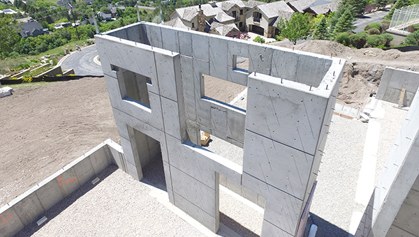
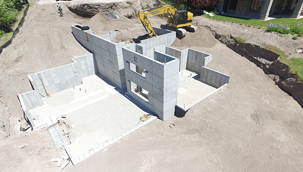
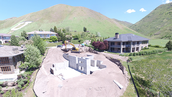
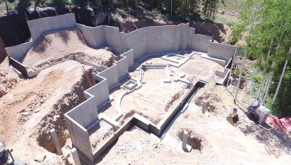
The Levy Residence, 2018 CFA Overall Grand Project of the Year by SCW Footings & Foundations, Inc., Salt Lake City, Utah.
Collecting the 2018 Grand Project of the Year
In the Spring of 2017, SCW Footings & Foundations of Salt Lake City, Utah completed construction on a project presenting quite unusual qualities when compared to traditional foundations seen across the landscape of both the CFA’s award programs and the traditional projects noted as single-family residential foundations. Where most concrete foundations simply establish a base for architecture, this project pulled the team of SCW into delivering architectural concrete that, in addition to providing the structure for the home, was made to be part of the visual aesthetic, with the skin and nuances many home owners today want from their home.
The project itself is not the ostentatious presentation of sheer size, volume and extreme contracting conditions that has been the moniker of this award program in years past. At just over 4,500 square feet (420 sq m) the project was sized among the more benign projects typically undertaken in the mountains and valleys of the lower Rockies. Yet, one is quick to take notice of this project after looking past the basic statistics. It features concrete walls that exceed 20 feet (6 m) with only a third of the total wall length less than 11 feet (3.4 m). These tall walls display a decorative concrete feature down the center of the floor plan, anchoring the foundation and the house itself into the landscape.
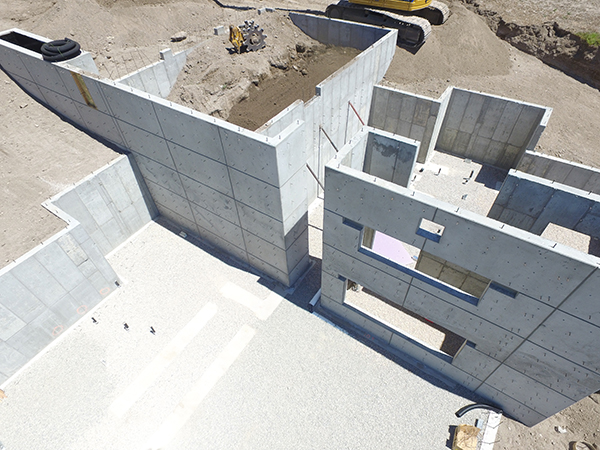
Submitting the project for the program, Dave Sheppard, project manager and estimator for SCW had this to say: “There aren’t many homes under 5,000 square feet that have these types of walls. Most noticeably, the feature that is a decorative concrete wall system down the middle of the home poured 20 feet and 6 inches (6.25 m) at its tallest point and spanned over 70 feet (21.3 m) from front to back.”
The SCW team describes a few unique and very intricate details that occur specifically in their notable wall. “The 4’ by 8’ (1.2m by 2.4m) smooth ply finish panels were showcased across all exposed faces of the wall,” states Sheppard. “These were outlined with chamfer strips and detailed with 18 faux cone tie holes in each panel. Overall, the finish covered nearly 1,600 square feet of wall.”
Companies that traditionally use manufactured handset forms for cast-in-place concrete foundations find a strong learning curve when they are given the challenge of producing a more contemporary, exposed concrete aesthetic like the snap-tie cone rhythm of a wall like this. When asked about their approach to this specialized aesthetic, Kirby Justesen, president of SCW Footings & Foundations, said, “Although we mostly form with aluminum panels, when we pour decorative concrete walls, whether that is board-form walls or traditional architectural walls with chamfer and cone ties, we use the Symon forming system. Symon forms allow us to more easily attach the boards or liners. Those boards can be wood planks, HDO plywood, or plastic/rubber liners. It just simply takes a lot more time to build and a lot more time to plan.”
SCW as a company has spent a lot of time experimenting with architectural concrete, as the Utah market has been trending toward a greater amount of the expressed concrete aesthetic in housing. “Over the years I developed an interest in decorative concrete and spent many years learning, discovering and trying new ways,” states Justesen. “This was mostly flatwork, counter tops, and vertical and horizontal overlays. It was during this time that I came to believe that the natural color of concrete is beautiful and gives the viewer a sense of strength and durable. About that time, we had architects drawing house plans with exposed concrete walls inside and out. The preferred choice was the board form look and to a lesser extent the traditional architectural walls with reveals and cone ties. I became very interested because it was a bit artsy and that appealed to me. We started learning how to pour the exposed walls with our regular production forms, Symon and Aluminum. We started with mockups that we poured in our yard so architects and owner could come and take a look. A bit to my surprise these exposed walls have really taken of in Utah. We now have two to four of these jobs going on continuously.”
SCW was recognized two years ago for another impressive feat of architectural concrete, involving the “board formed” appearance that has been very popular in the last ten years or so. The team at SCW is known throughout the region as the company contractors can turn to in order to mold concrete to fit the designer’s vision. Justesen believes it to be their attention to detail and craftsmanship that makes the difference. “This contractor was incredibly impressed with our portfolio found on our website (www.solidconcretewalls.com) and along with in-person site visits to other jobs, we were able to take them. We feel our architectural concrete is unmatched in the residential foundation industry in Utah, and we are fortunate with this opportunity that they agreed.”
But the challenge of a project like this, combining both size and complexity of the concrete work, does not come easy. Scheduling, Sheppard and Justesen believe, is an essential part of the success. Committing to such a project involves knowing it will require a crew that has perhaps the most experience and is larger than normal. While the standard residential foundation job is often characterized as a three-day project (given perfect conditions), the team at SCW know going into this type of a project that it will take weeks to complete. “Since projects like this can take weeks to complete, and we must be sure other jobs aren’t neglected because of them, we start by dedicating a project manager to the study of the project and pair him with a CAD draftsman in order to draw the details necessary to visualize the project from our perspective,” states Sheppard. “Architectural and even engineering plan sets just don’t deliver the detail we need,” says Justesen. “Therefore, our team redrafts the picture and details the wall heights, rebar schedules and step locations for our field crew so that they would not be hindered in any way.” This type of effort results in a completely new package of drawings that addresses each and every detail SCW will encounter on the project. All buck locations, panel sizes and locations, and every connection detail, are drawn fully to the satisfaction of the project manager before they get to the job site.
When asked how the company feels about the completion of this project and the recognition it now receives from the CFA Projects of the Year, Justesen offered, “These projects are fun to do and scary at the same time. We are always relieved when they turn out good. I love the look of durability and strength that exposed concrete walls have. When we have the chance to add a little artistry to our work it is enjoyable. When we receive industry recognition it is just icing on the cake.”
Known simply as the Levy Residence, this project was submitted in the category of single-family residence, 2,000 to 5,000 square feet. It was selected to be the signature project this year over 22 other projects, including nine projects weighing in at over 5,000 square feet.
Decorative Structural Concrete to Honor Heritage
Not every project seeking recognition needs to be a foundation. Every year, CFA seeks to celebrate the achievements of cast-in-place concrete from the breadth of the industry. Very near the site of the Concrete Foundations Convention 2017 stands the Demonbreun (pronounced “demon brun”) Street Bridge. It was designed to honor Nashville’s Railroad Heritage. While it opened in late October 2006, linking downtown Nashville with the midtown area, the project has only recently been uncovered by members of this Association as an example of the incredible artistry, ingenuity and craftsmanship that goes into modern cast-in-place concrete.
Located about 10 blocks from the Sheraton Downtown Grand where CFA hosted last year’s Convention, the bridge stretches nearly 774 feet across the gulch and CSX Railroad between 10th and 12th Avenue. It provides three lanes of traffic along with walkways for bikes and pedestrians. After spanning Nashville’s historic railroad gulch for nearly 75 years, the original structure was deteriorating and had to be closed in July 2004. The new $8.3 million viaduct includes unique architectural features that pay tribute to the city’s historic ties to the railroad and music industries. Scott System, a national associate member of the CFA, worked with Hawkins Partners landscape architects in Nashville, Tennessee to complete their vision of piers that resembled a locomotive engine. Other railroad motifs were also blended into the barrier walls and abutments. According to the landscape architect, Chris Whitis, “The ‘Context Sensitive Design’ factor of this project required the structure to incorporate elements of the immediate surroundings.” This translated into an artistic component inspired by the area’s railroad heritage. “The addition of the artistic piece that included custom form liners did not inflate the cost of the overall project,” Whitis said.

Demonbreun St. Viaduct, Nashville, TN. 2018 CFA Project of the Year for Non-Wall Structural Projects. Photo courtesy of Hawkins Partners Inc.
Scott Systems answered the Association-wide call for submittals to the 2018 competition once again after having received honorable mentions for a couple of years for work they had participated in. “In thinking about the awards program,” states Buck Scott, founder of Scott Systems, “I wanted to try and show something being done in concrete that has perhaps never been seen in old poured concrete.”
The tagline for Scott Systems is “The Art of Concrete Textures.” They have been involved in thousands of projects where patterning expressions in vertical concrete is desired and required. “We thought about the challenge from the architect and thought, ‘why not,’” said Scott. “So we produced an elastomeric liner to attach into the formwork. The result is stunning.” From the architects’ designs, employees at Scott System went to work developing the custom form liners made from urethane elastomer. They blocked the design using form shapes and incorporated various surface textures into their designs before producing the reverse image liner, a common approach to the complicated artistry they face regularly.
The art deco bridge serves as the major link between Nashville’s midtown and the new 2.1 million-square-foot Music City Center in downtown Nashville. The 300-foot-long bridge spans over the CSX railroad tracks. The project was completed five months ahead of schedule and was constructed under the project management of Bell & Associates of Brentwood, Tenn. The public works director, Billy Lynch, was quoted regarding the fast turn-around as saying it was, “a result of an unprecedented partnership between local and state governments and the fine work of TDOT’s contractor, Bell & Associates.” Add in the creative artistry produced by the liners produced by Scott Systems, and the result is clearly defining for the concrete industry and the 2018 Projects of the Year in the category of non-wall structural feature.
The Perrault Residence by SCW Footings & Foundations, Inc. of Salt Lake City, Utah. 2018 Project of the Year winner in the Over 5,000 sq.ft. project category.
The ‘Massive’ Foundation Still Impresses
Collecting a second award this year, SCW Footings & Foundations from Salt Lake City, Utah submitted the foundation known simply as the Perrault Residence with a footprint over13,000 square feet. Certainly, no stranger to large foundations (The Nowak Residence – 2016), the staff at SCW manages these projects knowing they have been involved because of their reputation.
“Many years ago, CFA brought in George Hadley as a guest speaker during the annual meeting we used to have during World of Concrete in Las Vegas,” states Justesen. “I learned that night probably the most important principle in subcontracting. It was this—you have three things to sell and they are; price, quality and timeliness. You can only ever deliver two…well, maybe in a recession you have to deliver three. My goal has always been to deliver quality and timeliness and to be the most progressive company willing to do the most difficult jobs, for a price. Many years of following this one principal is why I think we get a crack at biding all the largest residential homes found throughout these ski resorts along the Wasatch front.”
Reviewing the project photography, judges commented on how this job was filled with complexity. The team at SCW described how t was staged and poured in multiple phases, starting with the tallest, 28-foot retaining wall portion and ending with the shorter front 4-foot-tall walls. To achieve the strength and stability required for such tall walls, twelve separate 6-foot-long by nearly 25-foot-tall “deadmen” walls were added to the outside face to keep the wall plumb and true after backfilling. There were 70 corners throughout this job, adding complexity and time to the building process.
Concrete placement is not the only thing that makes these projects complex. The engineer identified over 20 base/embed plates throughout the job that were required to be cast into the footings and walls. “This is a very tedious task,” stated Shepherd. “We can’t have those misplaced or the future steel won’t fit properly.” In other words, what is cast in concrete is literally cast in stone, and the trades that followed them were relying on their accuracy to establish the success for the rest of the project.
The project location only further complicated the approach to the work. The Perrault Residence sits at the top of a mountain and has a beautiful view. SCW surveyed the approaches to the site using drones in order to have the best plan in place for getting concrete and pump trucks up there. Even with planning, however, getting the project set up properly was difficult.
All in all, they were successful. They began with 250 linear feet of 14-foot-wide by 24-inch-thick footings – that is 260 yards in one footing alone. “The terrain and changes in the footings were crazy on this project,” states Justesen. “They ranged from that thick all the way down to a typical 24-inch-wide continuous 12-foot footing. Perhaps the biggest elevation change we’ve faced, though. There was a total of 29 vertical feet between only five footing steps throughout this project.”
 A Foundation Prepared for the Big Move
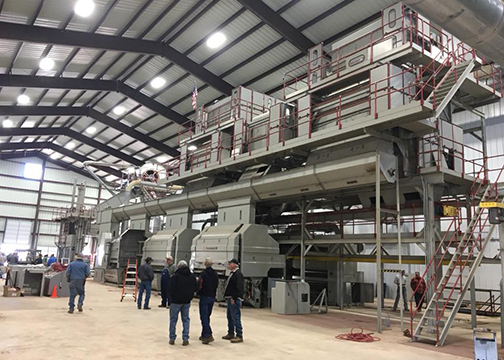
Not to be outdone by project scopes like that of “Big Dig,” Oklahoma is now the site of a massive cotton gin that was moved earlier this year from North Carolina. A machine of this magnitude requires a massive and complex foundation, and Basement Contractors of Oklahoma can fully describe the intricate details of matching a new foundation to an existing and functioning structure.
“The most complex part of this job was placing more than 1,000 anchors for the steel building and equipment,” states Mike Hancock, president for Basement Contractors. “The accuracy was stringent for the equipment to be re-used exactly as it was used in North Carolina, from where the cotton gin was being moved and had to be ready to go when it finally arrived.”
As if the anchors for all the equipment were not exacting enough, over the 38,500 square feet of concrete floor, the elevations needed to be perfect, so the equipment would fit together correctly. The main floor of the gin was raised three feet above the receiving floor, so the entire area was graded three feet up. The exterior was then cut down to place the footings and three-foot stem walls. “On a project of this size you cannot afford to be off fractions of an inch in elevations, as the result becomes inches of deviation at those heights and distances,” states Hancock. “Matching a grade in Oklahoma from a location halfway across the country to within one-fourth of an inch while matching each piece of equipment’s anchor bolt locations without the original plans was more than challenging.”
The footings stepped down at critical equipment locations for the cotton gin process. The equipment coming from North Carolina dictated the elevations that needed to be established in Oklahoma, with five separate elevations across the building pad. Mike Hancock added, “We just had to make sure and make the new construction match what the used equipment required.”
Entered in the category of agricultural projects, the Cotton Gin adds recognition for the broader spectrum of cast-in-place concrete projects by contractor members of the CFA. This project was massive and prescribed a tedious level of quality control to an industry that few might regard as having such attention detail. Flatwork and foundations alike challenged the extent of the experience this contractor had developed in building high-quality residential foundations and above-grade concrete homes.
 The Challenge of Repetition
Although CFA contractors are traditionally known for their work on single-family residential foundations, an increasing trend seen throughout the Association is the delivery of high-quality foundations for a wide variety of multi-family and townhome structures. Commercial foundations in both scope and approach, these projects challenge the coordination and mobilization of the standard residential foundation contractor. Along with being challenging, these can be among the most profitable.
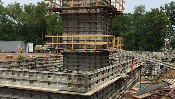
This year, chosen from an impressive amount of submissions (the most ever received in any one year), Purinton Builders (East Granby, Conn.) receives the Project of the Year award for Multi-Family Residential. “Ridge Road,” a project previously covered in Concrete Facts (Winter 2018), features a collaborative effort between Purinton and fellow CFA member, Bartley Corp (Silver Springs, Md.), to accommodate the exceptionally large project.
The 23,000-square-foot project required a schedule where one half of the footings, foundation walls and slabs were installed first, to permit the carpenters to begin. Then, the concrete work for the remaining half was completed while above-grade work proceeded. Having multiple trades on site added complications to the workflow; it was a project characteristic not often encountered by most cast-in-place concrete contractors on foundation projects.
“This project was extremely tedious and complex,” states Dennis Purinton, company president. “There were more than 1,300 anchor bolts on this project and we wet set only 600 of them. It was necessary to post-install many anchor bolts to ensure accuracy. It is a dedicated profit opportunity and we were able to do this using the dustless drilling system we have come to rely on. OSHA’s Silica Regulation has not been difficult for us to adapt to since moving to this system several years ago.”
Purinton Builders was suited for this project due to their quality control measures and their familiarity with a variety of added products. This foundation required 2,300 square feet of slab insulation, 560 linear feet of slab-edge thermal break and 23,000 square feet of Stego® vapor retarder. Also, in addition to the considerable number of anchor bolts, the team installed more than 400 linear feet of threaded rod for shear-wall hold-downs with 600 two-and-a-half-inch square washers for shear panels. The foundation schedule included 26 columns and pilasters, 2,500 linear feet of footings with haunches, and 8-foot by 14-foot by 24-inch interior pads with double-mat #9 rebar spaced at 12 inches on center in both directions.
Most recognizable on the Ridge Road project, however, was the 47-foot-tall cast-in-place elevator shaft. The requirements were that we could be no more than ½-inch out of square or no more than 1-inch out of plumb or the elevator would not fit. We complied with a 50% safety factor. The walls were eight inches thick with a double mat of #4 and #5 rebar spaced at 12 inches on center both horizontally and vertically. We used traditional aluminum formwork with an OSHA-compliant staging and guardrail system.
“Coordination, organization and collaboration, along with high-quality equipment,” states Purinton, “make jobs like this go very efficiently. The Ridge Road multi-family Project of the Year winner is yet another example of the breadth of concrete expertise and challenge-accepting confidence CFA contractors put forth.
 An Architectural Parking Structure Challenge
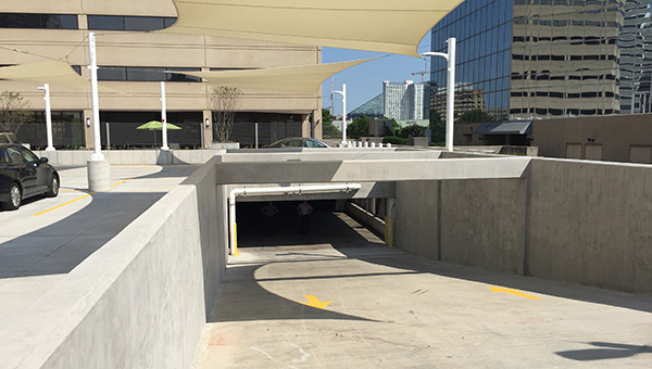
Bartley Corporation (Silver Springs, Md.) is the 2018 recipient of the Project of the Year category winner for Commercial Structure. The 1 East Pratt Street Plaza project incorporates an impressive variety of cast-in-place concrete delivered with high quality. The company has long held to their market commitment to both residential and commercial concrete projects, and yet they found themselves challenged by the technical nature of this project.
“The real challenge for us on this project,” states Jim Bartley, president of Bartley Corp, “was the fact we weren’t working with a traditional starting point for us. This project required us to work from an existing elevated parking deck in the center of the Baltimore inner harbor to create access to a plaza level converted into additional surface parking.”
The supporting ramp walls were continually sloped to maintain structural support for the angle of the ramp. They also extended above the ramp to the existing plaza level where the new parking deck was to be created.
This project consisted of 15,885 square feet of topping slab, a 954-square-foot ramp, and 220 linear feet of ramp walls that ranged in height from 1 to 8 feet and had thicknesses of 8, 12 and 22 inches. A total of 465 yards of concrete was placed with 224 yards located in the ramp walls. A total of 15,000 pounds of steel reinforcement was required in the relatively small project.
When asked about the most challenging features for the project, Bartley said it had to be the several new cast-in-place concrete beams that spanned the ramp opening being created. He said, “One of these beams was nearly 24 feet long and had an L-shape that was over 3 feet tall and 2 feet wide at the base, 18 inches wide at the top. We also cast two others that were of the same length but had cross sections of 12-by-12 inches and 18-by-12 inches.”
The project success was one of breaking the composition down into manageable quality-control steps. The walls supporting the ramp slab were built to the required slope, and then a special forming system was rented for the elevated ramp slab deck. Next, the walls were extended to their full height above the ramp slab and beams were added. The system used to control the pace and process of this project led to an impressive, completed work.
 Small Yet Mighty…Mighty Complex
While the big projects often deliver the wow factor in the annual consideration for Projects of the Year, the fact remains that “the devil is in the details,” and the small projects demonstrate the nuances and challenges met in every day contracting. This can certainly be said for this year’s recipient in the “Single-Family Foundation: Under 2,000 Square Foot” category, delivered by Custom Concrete (Westfield, Ind.), referred to as “Indian Lake.”
“For a project of only 1,500 square feet, this offered us a real challenge,” states Darin Hackman, VP of Residential Construction for Custom. “We had 67 yards of concrete in the walls but had seven steps for eight different wall heights ranging from 2 feet to 10 feet. We were stepping these walls every 3 feet along both sides.”
At just over 1,500 square feet, the project contained 387 linear feet of 8- and 11 ½-inch concrete walls. Along the sides of the house, pilasters were installed to give additional stability to the stepping wall structure. Perhaps the most unique feature of this small house foundation, however, is the nine-foot wall built at the back of the house, just to support the basement floor slab. “The house sits on a very steep hillside,” states Hackman. “The design required an 8-inch-by-9-foot tall wall just to get to basement floor grade. Coincidingly [sic], the garage walls we normally see at three feet in height were sloped from three to nine feet.”
To further demonstrate the severity of the site’s condition: a house of this size would normally require approximately 270 tons of gravel for the pad and fill. This house, however, required more than 730 tons of gravel, largely due to the 9-foot-tall rear frost wall condition.
In addition to the quality projects featured here as category winners and the Overall Grand Project of the Year, six additional projects received Honorable Mention this year. These Honorable Mentions include Summit at Lost Mountain (Herbert Construction Company, Marietta, Ga.), Freshwater Lane (Doggett Concrete Inc., Charlotte, N.C.), Lake House (Basement Contractors, Edmond, Okla.) and DKM (Custom Concrete, Westfield, Ind.), all projects from the single family, over 5,000 square feet category as well as Doyle Residence (SCW Footings & Foundations, Salt Lake City, Utah) and Waterford (Michel Concrete, Springfield, Ill.) from the single-family residence, 2,000 – 5,000 square feet.
More photos of these projects can be seen under “Association Awards” through the “Recognition” section of the CFA’s website, www.cfaconcretepros.org, along with archives of the annual project award recipients.