CFA Announces 2016 Safety Achievement Awards
The CFA announced the 2016 Safety Achievement Award recipients at CFA Convention 2016 in Myrtle Beach, SC on Saturday, July 23, 2016.
The Safety Achievement Awards program seeks to recognize the commitment to safety and risk management among the hundreds of professional cast-in-place contractors found in CFA membership. “Safety remains a top priority in our industry,” said Jim Baty, executive director of the CFA. “This program challenges contractors to demonstrate leadership by documenting their job-site and company-wide safety efforts. Recognizing safety achievements plays a vital role as the industry strives to demonstrate and promote the importance of job-site safety,” said Baty.
The CFA Safety Achievement Award program recognizes three defined contractor categories; that of Residential Foundation Contractor, All Concrete Contractor and Turn Key Contractor. In each category, company size is considered with sub-categories for total work hours of under 100k, 100k to 250k and over 250k work hours. Companies are recognized with awards for Best Overall Safety Achievement, Most Improved Safety Achievement, Zero Lost Time Accident.
Awarded in the category for BEST OVERALL SAFETY ACHIEVEMENT FOR 2015 WERE:
- CUSTOM CONCRETE COMPANY, INC. (All Concrete Contractor > 250k work hours)
- Stephens & Smith Construction Co., Inc., (Turn Key Contractor > 250k work hours)
- The Bartley Corp. (All Concrete Contractor 100k to 250k work hours)
- Walrite, LLC. (Residential Foundation Contractor < 100k work hours)
- Solid Concrete Walls, Inc. (Residential Foundation Contractor 100k to 250k work hours)
- Michel Concrete Construction (All Concrete Contractor < 100k work hours)
The recognition for MOST IMPROVED SAFETY WAS AWARDED TO STEPHENS & SMITH CONSTRUCTION CO., INC.
ZERO LOST TIME ACCIDENT AWARDS went to:
- WALRITE, LLC
- MICHEL CONCRETE CONSTRUCTION, INC.
Along with these major awards given at the 2016 CFA Awards Gala, Executive Director Baty also recognized 2016 Project of the Year Awards and the 2016 Professional Achievement Awards.
Visit the CFA Safety Awards online for more information on participating.
Putting Sustainability Where Our Mouth Is
Take a poll of constituents in the public domain or even within the concrete construction sector that asks what the top buzz words are today and arguably one of them that will surface at a high percentage is sustainability. Whether forced by regulation or encouraged by intuition, the drive for sustainability in our homes, our jobs and throughout the landscape of the construction industry is for all tense and purpose a new playing field. I’ve heard many describe it as “the new norm.” No, not the big guy at the end of the bar soaking his mediocrity in suds.
As Executive Director for this Association I have the privilege of being at the table for the Concrete and Masonry Related Associations (CAMRA). This collaboration brings together all interests in our segment of the construction industry to provide the 50,000 ft perspective on our industry and the competition. CAMRA has also begun to shape initiatives that all or specific subsets can hone direction and pool resources to achieve something greater as a whole. This is, in many respects, done for the sake of sustainability both for the concrete industry as well as for the future of such collaboration. One of the aspects of each of you belonging to a networking group like the CFA is that your small (relative) voice can be amplified and heard at a much greater level through us. This is the same sense I have at CAMRA where the CFA voice is amplified and at times considered a lead voice.
At CAMRA, within the CFA guiding efforts and likely at each of your businesses, in response to the pressures placed on the building industry, the drive for true sustainability has to be present and discussed. Whether it is considered a “fad” like the personal computer or the cellphone or truly a foundational part of tomorrow as it is today, for the moment there is no denying that moves to be more sustainable have a positive influence, even if it is limited to morale.
With this in mind, you should ask the question what is the CFA doing for sustainability? Dramatic efforts have been put forth in the last year here at CFA HQ to consider sustainability a priority. We have committed our entire communication history to digital media including records for membership, transactions and CFA association management. Perhaps you’ve noticed our emphasis on e-billing. CFA has converted all A/R and as much of A/P as possible over to electronic notifications and transactions. These have reduced our paper consumption to barely a case per year and lowered our recycling substantially. Were it not an election year, our recycling volume might be even lower. Likewise, we continue to promote ways you can connect to this great network without requiring travel or expensive participation. While we know it is of tremendous benefit to be physically present, we also know how much of a challenge it is and that virtual connection is the very best next option.
We are doing a lot to make sustainability paramount and to borrow the phrase from the Ford Motor Company, “Job 1”. Being sustainable in our work efforts has definitely made an impact on our efficiency, on our expediency and also on our morale. We hope you feel it too.

CFA Executive Director James Baty jbaty@cfawalls.org
Privileged To Serve
I am honored to be the new President of the CFA and I thank everyone for all the support I have received. In the next two years I hope to be able to share some of the knowledge I have amassed over the last 32 years, much of that directly due to becoming actively involved as a member of the CFA.
Why is it so important to be a CFA member? The list of reasons is actually very long, but of importance to all of us is: PROFIT and KNOWLEDGE.
I have been a CFA member for 17 years and in every one of those years, I have received information and guidance that changed some area of our business, making us more efficient and, therefore,more profitable. Before becoming a member, I truly believed that I had the best forming system and all the knowledge I needed. There was no way I could become more efficient and how could technology possibly help me be more profitable. To me, there was no need to become a CFA member. Was I ever wrong!!
Participation = MORE PROFIT and MORE KNOWLEDGE
In 1999, I received a gift of membership for one year from one of our long time CFA members, Cranes and Equipment, encouraging me to join and participate. I continued paying the membership dues and enjoyed reading CFA Facts and other materials I received from the CFA. I found this information to be useful, but I was not actively attending the summer convention. A winter meeting at the World of Concrete was my introduction to CFA events. What an eye opener! There were actually people in the same business I was in who openly and willingly wanted to help me grow my business and increase my knowledge. After believing I could never afford to take time off from work for 2 or 3 days in the summer, I attended my first convention in 2001. I was amazed at the quality and variety of educational seminars and how much I learned from each of them. From that point on, I knew I couldn’t afford NOT to go! I have come away from every meeting with ideas, knowledge and product information that have helped me to become more efficient and more profitable. The camaraderie and lifelong friends I have found as a CFA member have a value that is immeasurable.
There are many CFA membership benefits…here are two:
The CFA 360 Insurance Program has been in effect for about a year now. This is one benefit that can show directly on your bottom line and a number of members have seen considerable savings in their business insurance premiums. This group insurance program was developed specifically for our industry by Arthur J. Gallagher and Co. and seeks to help members control their insurance costs through a variety of programs such as an industry specific safety program and sample contracts to be utilized when hiring subcontractors. The program continues to grow with additional benefits to be available in the future. Having an insurance agent that is your partner and seeks to protect your best interests is truly a valuable benefit.
The other benefit that I believe is extremely valuable is the ability to call CFA staff to obtain assistance when confronted with a building official who may not understand code. Some CFA members and CFA staff hold seats on ACI committees and CFA staff participate in the Building Code Process. They are a valuable source of information and have the ability to provide documentation to members to assist them in resolving disagreements or issues with local code officials. This is a benefit I have utilized on more than one occasion and is, by itself, well worth the cost of an annual membership.
I believe it is important for all of us to contribute to the industry that has supported us and allowed us to profit by it. The ability to share knowledge, ask questions, and contribute to strengthening our industry is huge. Please help us to continue to support a great industry by becoming a member. Your participation and membership will provide valuable returns in more ways than one.

CFA President (2016-18) Dennis Purinton of Purinton Builders Inc. purintonbuilders@yahoo.com
Code Minimum Foundation Heights Above Grade Are Important
As seen in The Washington Post, this Ask the Builder article by Tim Carter reinforces the information that has been presented for years by the Concrete Foundations Association.
Carter provides sound advice: “keep the foundation well above grade. And also make sure the grade falls away from the foundation.” To be specific, the 2015 International Residential Code (IRC) requires the foundation to be 4 inches above the finished grade when covered by a masonry veneer or 6 inches elsewhere. The slope of the finished grade must be maintained at a minimum of 6 inches of fall within 10 feet.
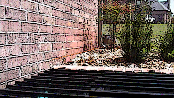
This residential structure with masonry cladding has landscaping and finished grade (around front) extending up onto the brick and above the height of the wood sill plate indicated by the orange line at the first exposed mortar joint.
According to Carter, building codes from “not too long ago” require a minimum of least six inches of foundation showing above the soil grade, and at least six inches of fall in the soil in the first ten feet away from the house. Carter recommends building a foundation at least 18 inches higher than the surrounding soil, and using dirt dug from the basement to make a “long gentle slope” away from the foundation.
Coming Out On Top: CFA’s Projects of the Year Elevate Craftsmanship
Mount Vernon, IA Aug 31, 2016 – The Concrete Foundations Association (CFA) – the recognized voice and authority for the residential concrete industry, announced the 2016 Projects of the Year award recipients at CFA Convention 2016 in Myrtle Beach, S. Car. on Saturday, July 23, 2016. Three projects were recognized as award winners including the Grand Overall Project of the Year and categorial winners of Commercial concrete project and mid-size Single Family Residential along with two additional projects receiving Honorable Mention.
Each winter, the Concrete Foundations Association opens a competition to its membership for a broad spectrum of cast-in-place concrete projects. These projects evidence the skill, quality, craftsmanship and at times creativity of today’s cast-in-place contractor. Many of these projects are quickly covered up and the achievement lost visually to the project supported above it. Some, however, become the framework expressed through masterful works of concrete technology and construction. This year’s Grand Project of the Year accomplishes all of this and sets new standards for aesthetic value in residential structural concrete work. The rest of the project awards complete the portfolio for continued excellence in the field of cast-in-place concrete.
The “Great Recession” now firmly in the review mirror has left an indelible fingerprint on today’s concrete contracting company. This fingerprint evidences the extreme resiliency of the American concrete contractor when everything is on the line. It also evidences, through such resiliency, the creativity to apply experience and ability toward new, unique work when necessary. In the end, it is often this uniqueness that becomes a new expertise and ultimately supports new architectural trends.
Grand Project of the Year: The Nowak Residence – SCW Footings & Foundations
Single Family Residence Foundation > 5,000 sq.ft. | Salt Lake City, Utah
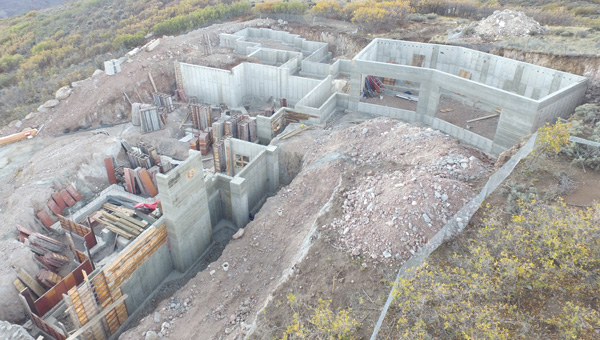
Taking the top honors in this year’s CFA Projects of the Year competition is a large residential foundation combined with above-grade concrete features set in the Salt Lake City, Utah region. The project is one in a cascading series of projects evidencing a transformation of style, construction practice and collaboration for the team at SCW Footings & Foundations. President and CEO, Kirby Justesen talks candidly about the maturation of a more architectural trend for the residential concrete in his market. “This residence is really one of a great many we’ve had our hands in over the last several years,” states Justesen. “The architecture in our market has changed to a contemporary or more modern style. We have been working hard to transform our business to be responsive to the desires of the home owners and collaborative with architects to achieve constructions we believe are much more timeless.
Natural concrete, while easily considered a more brutal or raw form of architecture from the Post Modernism period, is proving to be the signature form and finish to simplify residential structures and create a strong, warm and aesthetic framework for the living spaces. Justesen and the team at SCW have delved into the forming and patterning of concrete in new ways to remain economical with their modular forming systems while optimizing the architectural creativity of concrete.
“The Nowak residence implemented board form as a selected concrete finish,” continues Justesen, “one finish we have put considerable effort into since recession to achieve greater variety and creativity.” After much work developing the technique and perfecting the process of selecting and preparing the wood for the forming process, they began small and have progressed to some very impressive concrete works with an exposed board form texture on the interior as well as exterior, below and above grade.
“This was certainly a complex job this past year based on sheer size and square footage alone,” states John Graber, estimator for SCW. “However, when you add in the board formed concrete throughout the entire project, it more than doubles labor time for the project and is complicated by things like wood source and quality. The best way to overcome these challenges were to make sure everything and everyone was on the same page regarding schedule, final expectations as well as communication.”
The Nowak Residence consists of technical challenges including multiple footings steps accounting for a total of 34 feet of vertical change in footing elevation throughout the project. These footings total 1,024 linear feet of continuous ranging from 24” to 48” wide and many 36” square up to 96” square footing pads, all with cast in place moment frame baseplates. Not surprisingly due to the extreme elevation changes, this project has 15 different wall heights and 6 different wall thicknesses throughout.
Throughout these walls, the biggest factor by far for complexity was the application of the architectural board form finish. All exterior exposed faces of the foundation wall were designed to receive the board form finish. SCW individually stapled over 3,000 sq.ft. of 4”, 6”, 8” and 12” wide pine planks to achieve an enhanced wood grain texture in the concrete. The finished aesthetic became the signature statement in the interior design for the home owner.
When asked about the approach to this project specifically coming from the culture of their company, Graber had this to say; “when we were awarded the job, we immediately placed one of our best project managers in charge of the project, one with a vast knowledge of complex jobs and instrumental in our board form application. We assigned our best crew leader and crew to the job as well to ensure consistency. Technically, the project was re-drawn in house in CAD, per the architect’s plans, in order to prepare for layout; determine wall heights; and create schedules for all bucks, blockouts and any straps, bolts, embed plates, etc. out the top of walls. When we got into the field, this CAD preparation led directly to extremely accurate layout using the Leica Geosystems (CFA Member) iCONstruct robot/software. The project was scheduled weeks in advance to ensure that all parties were prepared and ready.
The Nowak Residence was selected as the Grand Project of the Year by popular vote through CFA’s website at www.cfawalls.org. It also was the winning entry in the Single Family Foundations > 5,000 sq.ft. This project was also selected at the World of Concrete as the Best in Show for 2016 by visitors to the CFA booth.
The Nowak Residence Project Specifications:
| Size: (Total Lin.Ft.) | 1,082 | Size: (Total Sq.Ft.) | 8,408 | |
| Walls: (total yds) | 450+ | Footings: (total yds) | 200+ | |
| Walls: (total steel) | 47,000 lbs | Footings: (total steel) | 5,700 lbs | |
| Wall Heights: (ft. & in.) | 4’-0” – 20’-0” | |||
| Wall Thickness: (ft. & in.) | 8” – 24” | |||
Howell Mill – Herbert Construction Company
Commercial Structure | Atlanta, Georgia
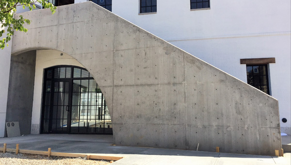
Since 2010, companies have been submitting commercial projects to the CFA’s annual Projects of the Year competition to evidence the growth that has occurred of cast-in-place foundation technology and expertise throughout those larger or broader markets. Often awarded are very large and deep, as well as challenging foundation systems in urban settings. This year, popular vote has selected a strong architectural application for cast-in-place concrete for Howell Mill. Submitted and constructed by Herbert Construction Company of Marietta, Georgia, the project consisted of concrete work on two separate buildings within a retail and restaurant complex, including an exposed concrete wall with a challenging arched opening.
The first building required highly technical work from the Herbert Construction team to achieve an architectural concrete wall serving as the focal point of the entire project. “The architect and owner were very specific about the look they wanted for the architectural wall,” states Amanda Morris, VP of Operations for Herbert Construction Company. “We chose an MDO plywood forming system to form the wall and accessed the experience of our firm’s VP of Construction, Mike Herbert, to lead this method. Forms for each wall section were built on the ground and tilted up into place with our boom truck. A form tie hole pattern was selected to provide an aesthetic, uniform appearance.”
One side of the concrete wall will be experienced as shoppers ascend a stairway attached to the wall. The other face of the wall will be seen at the pedestrian level by visitors to the complex. A large, 12’-2½” radius opening was created in the 18’-6” tall architectural wall, which restaurant-goers will walk through to enter the trendy restaurant on the ground floor.
Squeezed into a very tight location, the second building involved concrete footings and walls to create a Terrace Level foundation. Herbert Construction was required to shore the existing soil to allow for a safe working area for crews. The main level floor itself consisted of concrete placed on metal decking. This floor is supported by 168 linear feet of continuous angle cast-in the top of the 12’-0” tall wall. The wall also contained 18 embedded beam plates in the face of the wall, and 80 anchor bolts in the top of the wall for steel columns as well as a cast-in door frame and three window openings.
Placing the concrete for these walls was challenging as both consisted of double mat steel reinforcement bars and vertical contraction joints with waterstop. “We consulted with the general contractor through several variations of this project over the course of two years,” stated Doug Herbert, President of Herbert Construction Co. “Once the development was finally released for construction, he knew we were the ideal concrete contractor for this type of project.”
The hard work paid off and while not as large as some commercial projects receiving recognition in this program or seen throughout the industry as a whole, this was a highly technical project. “This project required more pre-planning than projects we’ve done that were many times larger,” states Morris. “The general contractor, architect and owner were all extremely happy with the appearance of the architectural concrete wall that we constructed. The architect stated that it was the best architectural concrete wall he has seen, and asked us to look at other projects in his pipeline, including a project in Florida,” states Herbert.
Howell Mill Project Specifications:
| Size: (Total Lin.Ft.) | 219 | Size: (Total Sq.Ft.) | 1800 | |
| Walls: (total yds) | 106 | Footings: (total yds) | 25.5 | |
| Total steel (footings & walls): | #4 – 9,303 lin. ft.
#5 – 8,975 lin. ft. #6 – 305 lin. ft. |
|||
| Wall Heights: (ft. & in.) | Five total from 9’-3” to 18’-6” (sloped down to 6’-4”) | |||
| Wall Thickness: (ft. & in.) | Four total from 8” to 16” | |||
Delp Foundation – Custom Concrete Company
Single Family Residence Foundation 2,000 to 5,000 sq.ft. | Greenwood, Indiana
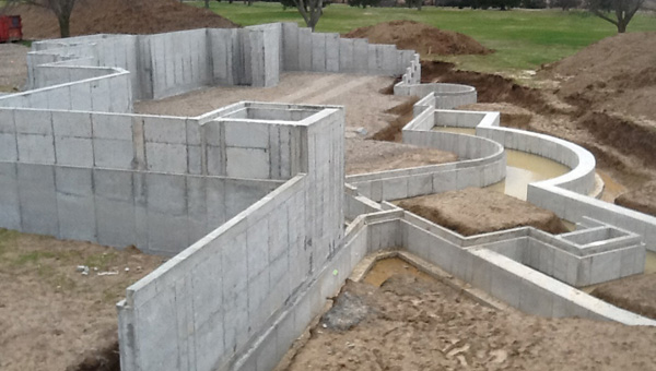
The average size home in the United States last year reached 2,600 sq.ft. according to the Census Bureau. Receiving the popular vote for top residential foundation in this size range, however, was a project that certainly can’t be considered average or ordinary, the Delp Residence completed by Custom Concrete Company out of Westfield, Indiana.
The signature for this foundation project is quickly evident in the four walls with radius sections, all having significant dimensions, the largest radius which was 270 degrees. “The biggest challenge we face on these projects is always the difficulty of the layout and forming for the radius walls,” states Jason Ells, Executive Director of Operations for Custom Concrete. “We find it essential to start with good, consistent communication on the project and developing our own thorough CAD drawings. These allow us to communicate any issues effectively with the project team and ultimately send clean CAD prints and points for the robotic layout system out to the field.”
The walls for this residence were not just a series of straight lines and curved connectors. The walls were also designed with multiple steps and with varying brick ledge or wall thickness recess heights. A total of 169 layout points to achieve the layout were produced and delivered to the site efficiently with the company’s robotic equipment.
“We were referred this job based on our commitment to quality and consistency,” states Ells. “We approached it with the same scrutiny and quality control that we do each and every project. When we were all taught to ‘measure twice and cut once’, we take that to heart and make sure that every move is planned, calculated and double-checked to make sure it is delivered intentionally for a satisfied customer.”
Delp Foundation Project Specifications:
| Size: (Total Lin.Ft.) | 841 | Size: (Total Sq.Ft.) | 4,846 | |
| Walls: (total yds) | 136 | Footings: (total yds) | 68 | |
| Walls: (total steel) | 3,300 lbs | Footings: (total steel) | 2,800 lbs. | |
| Wall Heights: (ft. & in.) | Nine total from 2’-4”to 13’-0” | |||
| Wall Thickness: (ft. & in.) | Seven total from 8” to 20” | |||
Honorable Mentions
This year, two additional projects were selected to receive honorable mention from the popular voting taking place at both the World of Concrete and online through the CFA’s website. Those projects were both single-family residential foundations in the > 5,000 sq.ft. category submitted by Doggett Concrete (Kingswood) and Herbert Construction Company (Private Residence).
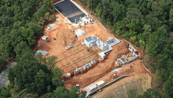
A monster residential foundation complex for an unnamed private residence constructed by Herbert Construction Company of Marietta, GA
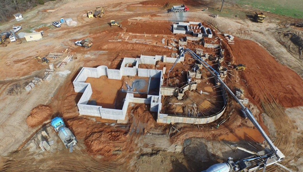
The Kingswood residential foundation by Doggett Concrete, Inc. – Charlotte, NC
More Information
“CFA Projects of the Year” is an exclusive and free opportunity for members of the Association to submit and display their pride in quality of design, craftsmanship and achievement. Projects are submitted each winter for presentation by popular vote at the World of Concrete and online. For more information on these projects, visit the “CFA Projects of the Year” at CFA’s website, www.cfawalls.org under Recognition, where you will find more images and facts for this year’s winners, the historical archives for the competition and information on the competition itself including voting basis and entry guidelines.
If you would like more information, please contact CFA Executive Director, James Baty, phone 866-232-9255 or jbaty@cfawalls.org.
The CFA is a voluntary, nonprofit association that brings together concrete contractors and professionals nationwide to improve the quality of cast-in-place concrete walls and foundations. The CFA provides promotional materials, educational seminars and networking opportunities to its members and the industry. CFA also works on behalf of its members and the entire industry to develop support and influence code bodies. For more information about CFA, please visit www.cfawalls.org or call 866-CFA-WALL (232-9255).
2016 Projects of the Year: Custom Concrete Company
Single Family Residence Foundation 2,000 to 5,000 sq.ft.
Delp Foundation
Custom Concrete Company
Greenwood, Indiana
The average size home in the United States last year reached 2,600 sq.ft. according to the Census Bureau. Receiving the popular vote for top residential foundation in this size range, however, was a project that certainly can’t be considered average or ordinary, the Delp Residence completed by Custom Concrete Company out of Westfield, Indiana.
The signature for this foundation project is quickly evident in the four walls with radius sections, all having significant dimensions, the largest radius which was 270 degrees. “The biggest challenge we face on these projects is always the difficulty of the layout and forming for the radius walls,” states Jason Ells, Executive Director of Operations for Custom Concrete. “We find it essential to start with good, consistent communication on the project and developing our own thorough CAD drawings. These allow us to communicate any issues effectively with the project team and ultimately send clean CAD prints and points for the robotic layout system out to the field.”
The walls for this residence were not just a series of straight lines and curved connectors. The walls were also designed with multiple steps and with varying brick ledge or wall thickness recess heights. A total of 169 layout points to achieve the layout were produced and delivered to the site efficiently with the company’s robotic equipment.
“We were referred this job based on our commitment to quality and consistency,” states Ells. “We approached it with the same scrutiny and quality control that we do each and every project. When we were all taught to ‘measure twice and cut once’, we take that to heart and make sure that every move is planned, calculated and double-checked to make sure it is delivered intentionally for a satisfied customer.”
Project Specifications:
- Size
- Total Lin. Ft. : 841
- Total Sq. Ft. : 4,846
- Walls: 136 yds
- Footings: 68 yds
- Steel Used
- Walls: 3,300 lbs
- Footings: 2,800 lbs
- Wall Heights: Nine total from 2’4″ to 13′
- Wall Thickness: Seven total from 8″ to 20″
2016 Projects of the Year: Commercial Structure
Commercial Structure
Howell Mill
Herbert Construction Company
Atlanta, Georgia
Since 2010, companies have been submitting commercial projects to the CFA’s annual Projects of the Year competition to evidence the growth that has occurred of cast-in-place foundation technology and expertise throughout those larger or broader markets. Often awarded are very large and deep, as well as challenging foundation systems in urban settings. This year, popular vote has selected a strong architectural application for cast-in-place concrete for Howell Mill. Submitted and constructed by Herbert Construction Company of Marietta, Georgia, the project consisted of concrete work on two separate buildings within a retail and restaurant complex, including an exposed concrete wall with a challenging arched opening.
The first building required highly technical work from the Herbert Construction team to achieve an architectural concrete wall serving as the focal point of the entire project. “The architect and owner were very specific about the look they wanted for the architectural wall,” states Amanda Morris, VP of Operations for Herbert Construction Company. “We chose an MDO plywood forming system to form the wall and accessed the experience of our firm’s VP of Construction, Mike Herbert, to lead this method. Forms for each wall section were built on the ground and tilted up into place with our boom truck. A form tie hole pattern was selected to provide an aesthetic, uniform appearance.”
One side of the concrete wall will be experienced as shoppers ascend a stairway attached to the wall. The other face of the wall will be seen at the pedestrian level by visitors to the complex. A large, 12’-2½” radius opening was created in the 18’-6” tall architectural wall, which restaurant-goers will walk through to enter the trendy restaurant on the ground floor.
Squeezed into a very tight location, the second building involved concrete footings and walls to create a Terrace Level foundation. Herbert Construction was required to shore the existing soil to allow for a safe working area for crews. The main level floor itself consisted of concrete placed on metal decking. This floor is supported by 168 linear feet of continuous angle cast-in the top of the 12’-0” tall wall. The wall also contained 18 embedded beam plates in the face of the wall, and 80 anchor bolts in the top of the wall for steel columns as well as a cast-in door frame and three window openings.
Placing the concrete for these walls was challenging as both consisted of double mat steel reinforcement bars and vertical contraction joints with waterstop. “We consulted with the general contractor through several variations of this project over the course of two years,” stated Doug Herbert, President of Herbert Construction Co. “Once the development was finally released for construction, he knew we were the ideal concrete contractor for this type of project.”
The hard work paid off and while not as large as some commercial projects receiving recognition in this program or seen throughout the industry as a whole, this was a highly technical project. “This project required more pre-planning than projects we’ve done that were many times larger,” states Morris. “The general contractor, architect and owner were all extremely happy with the appearance of the architectural concrete wall that we constructed. The architect stated that it was the best architectural concrete wall he has seen, and asked us to look at other projects in his pipeline, including a project in Florida,” states Herbert.
Project Specifications:
- Size
- Total Lin.Ft. : 219
- Total Sq.Ft. : 1800
- Walls: 106 yds
- Footings: 25.5 yds
- Steel Used (footings & walls)
- #4 – 9,303 lin. ft.
- #5 – 8,975 lin. ft.
- #6 – 305 lin. ft.
- Wall Heights: Five total from 9’3″ to 18’6″ (sloped down to 6’4″)
- Wall Thickness: Four total from 8″ to 16″
2016 Projects of the Year: Single Family Residence Foundation (>5,000 sq.ft)

Grand Project of the Year
Single Family Residence Foundation >5,000 sq.ft.
The Nowak Residence
SCW Footings & Foundations
Salt Lake City, Utah
Taking the top honors in this year’s CFA Projects of the Year competition is a large residential foundation combined with above-grade concrete features set in the Salt Lake City, Utah region. The project is one in a cascading series of projects evidencing a transformation of style, construction practice and collaboration for the team at SCW Footings & Foundations.
President and CEO, Kirby Justesen talks candidly about the maturation of a more architectural trend for the residential concrete in his market. “This residence is really one of a great many we’ve had our hands in over the last several years,” states Justesen. “The architecture in our market has changed to a contemporary or more modern style. We have been working hard to transform our business to be responsive to the desires of the home owners and collaborative with architects to achieve constructions we believe are much more timeless.
Natural concrete, while easily considered a more brutal or raw form of architecture from the Post Modernism period, is proving to be the signature form and finish to simplify residential structures and create a strong, warm and aesthetic framework for the living spaces. Justesen and the team at SCW have delved into the forming and patterning of concrete in new ways to remain economical with their modular forming systems while optimizing the architectural creativity of concrete.
“The Nowak residence implemented board form as a selected concrete finish,” continues Justesen, “one finish we have put considerable effort into since recession to achieve greater variety and creativity.” After much work developing the technique and perfecting the process of selecting and preparing the wood for the forming process, they began small and have progressed to some very impressive concrete works with an exposed board form texture on the interior as well as exterior, below and above grade.
“This was certainly a complex job this past year based on sheer size and square footage alone,” states John Graber, estimator for SCW. “However, when you add in the board formed concrete throughout the entire project, it more than doubles labor time for the project and is complicated by things like wood source and quality. The best way to overcome these challenges were to make sure everything and everyone was on the same page regarding schedule, final expectations as well as communication.”
The Nowak Residence consists of technical challenges including multiple footings steps accounting for a total of 34 feet of vertical change in footing elevation throughout the project. These footings total 1,024 linear feet of continuous ranging from 24” to 48” wide and many 36” square up to 96” square footing pads, all with cast in place moment frame baseplates. Not surprisingly due to the extreme elevation changes, this project has 15 different wall heights and 6 different wall thicknesses throughout.
Throughout these walls, the biggest factor by far for complexity was the application of the architectural board form finish. All exterior exposed faces of the foundation wall were designed to receive the board form finish. SCW individually stapled over 3,000 sq.ft. of 4”, 6”, 8” and 12” wide pine planks to achieve an enhanced wood grain texture in the concrete. The finished aesthetic became the signature statement in the interior design for the home owner.
When asked about the approach to this project specifically coming from the culture of their company, Graber had this to say; “when we were awarded the job, we immediately placed one of our best project managers in charge of the project, one with a vast knowledge of complex jobs and instrumental in our board form application. We assigned our best crew leader and crew to the job as well to ensure consistency. Technically, the project was re-drawn in house in CAD, per the architect’s plans, in order to prepare for layout; determine wall heights; and create schedules for all bucks, blockouts and any straps, bolts, embed plates, etc. out the top of walls. When we got into the field, this CAD preparation led directly to extremely accurate layout using the Leica Geosystems (CFA Member) iCONstruct robot/software. The project was scheduled weeks in advance to ensure that all parties were prepared and ready.
The Nowak Residence was selected as the Grand Project of the Year by popular vote through CFA’s website at www.cfawalls.org. It also was the winning entry in the Single Family Foundations > 5,000 sq.ft. This project was also selected at the World of Concrete as the Best in Show for 2016 by visitors to the CFA booth.
Project Specifications:
- Size
- Total Lin.Ft.: 1,082
- Total Sq.Ft.: 8,408
- Walls: 450+ yds.
- Footings: 200+ yds.
- Steel Used
- Walls: 47,000 lbs
- Footings: 5,700 lbs
- Wall Height: 4′ to 20′
- Wall Thickness: 8″ to 24″
CFA ANNOUNCES 2016 TOP SAFETY AWARDS
Mount Vernon, IA Aug 29, 2016 – The Concrete Foundations Association (CFA) – the recognized voice and authority for the residential concrete industry, announced the 2016 Safety Achievement Award recipients at CFA Convention 2016 in Myrtle Beach, SC. on Saturday, July 23, 2016.

The Safety Achievement Awards program seeks to recognize the commitment to safety and risk management among the hundreds of professional cast-in-place contractors found in CFA membership. “Safety remains a top priority in our industry,” said Jim Baty, executive director of the CFA. “This program challenges contractors to demonstrate leadership by documenting their job-site and company-wide safety efforts. Recognizing safety achievements plays a vital role as the industry strives to demonstrate and promote the importance of job-site safety,” said Baty.
The CFA Safety Achievement Award program recognizes three defined contractor categories; that of Residential Foundation Contractor, All Concrete Contractor and Turn Key Contractor. In each category, company size is considered with sub-categories for total work hours of under 100k, 100k to 250k and over 250k work hours. Companies are recognized with awards for Best Overall Safety Achievement, Most Improved Safety Achievement, Zero Lost Time Accident.
Awarded in the category for Best Overall Safety Achievement for 2015 were Custom Concrete Company, Inc. (All Concrete Contractor > 250k work hours), Stephens & Smith Construction Co., Inc., (Turn Key Contractor > 250k work hours), The Bartley Corp. (All Concrete Contractor 100k to 250k work hours), Walrite, LLC. (Residential Foundation Contractor < 100k work hours), Solid Concrete Walls, Inc. (Residential Foundation Contractor 100k to 250k work hours), and Michel Concrete Construction (All Concrete Contractor < 100k work hours).
The recognition for Most Improved Safety was awarded to Stephens & Smith Construction Co., Inc., and Zero Lost Time Accident Awards went to Walrite, LLC and Michel Concrete Construction, Inc.
Along with these major awards given at the 2016 CFA Awards Gala, Executive Director Baty also recognized 2016 Project of the Year Awards and the 2016 Professional Achievement Awards.
ABOUT CONCRETE FOUNDATIONS ASSOCIATION
The Concrete Foundations Association (CFA) is the recognized voice and authority for the residential concrete industry. Originally formed as the Poured Concrete Wall Contractors of America, Inc. (PCWCA), the CFA was formed in 1974 to serve the interests of poured wall contractors. The CFA has members throughout the U.S. and Canada as well as overseas representing all aspects of the cast-in-place industry including construction, design and manufacturing. Member firms are diverse in size and volume as well as business models with many operating across residential, agricultural and commercial markets. For more information, visit www.cfawalls.org or contact CFA at 319-895-6940.
SCHWING AMERICA NAMES NEW LEADERSHIP TEAM
|
St. Paul, MN (August 18, 2016) – Schwing America Inc. (SAI) (http://info.schwing.com/e/83972/2016-08-19/5l42vw/150439240) announced today its new leadership team of Bill Murray and Tom O’Malley following the resignation last week of former CEO, Brian Hazelton. Bill Murray, CFO for the past four years at SAI, has been named as CEO effective immediately. For two years prior to that, Murray held the position of Chief Restructuring Officer and independent Board Member. Over his 30-year business career, Murray has held senior level finance, operating and consulting positions in several companies including divisions of Daimler Chrysler and General Motors. Tom O’Malley has been promoted to Senior Vice President of Sales and Marketing, capping off a career of nearly 20 years at Schwing in various sales and marketing roles. Prior to Schwing, O’Malley had worked for Putzmeister America and Rotec Industries. Both Murray and O’Malley will serve on the Board of Directors of Schwing America. Rounding out the senior leadership team, Lisa Kraft-Kujawa will continue to serve as VP of Human Resources and Administration. Kraft-Kujawa joined Schwing last year after a consulting position with the organization. Joseph Schnittker, Director of Engineering & Design of Schwing Group, based in Herne, Germany will also help guide the company with direct responsibility and co-ordination of the Engineering and Research and Development groups in Herne and the Minnesota facilities. “I am confident in this team’s ability to continue to advance Schwing America as the premium concrete product manufacturer in North America,” said Dr. Gunther Abolins, Managing Director of Schwing Group in Herne, Germany. “They will continue to lead our talented team of senior leaders and dedicated employees to provide the best products and services for our current and future customers.”
### About Schwing America Schwing America is part of the Schwing Group, headquartered in Herne, Germany with manufacturing facilities, as well as sales and service centers, globally. Located in the St. Paul suburb of White Bear Township, MN, Schwing America manufactures industry leading concrete pumps, mixer trucks, reclaimers and genuine parts for sale and distribution in North and Latin America. (http://info.schwing.com/e/83972/2016-08-19/5l42vw/150439240 |