Water: Is It The Basement Contractor’s Worst Enemy?

Author: Mike Hancock, President Basement Contractors 6300 S. Industrial Blvd. Edmond, OK 73034
Sit down at any contractor’s round table and start a discussion about the predominant headache or source of callbacks for basements and you are likely to get common agreement that it is water or moisture. The presence of moisture is a sure sign to the homeowner that a) something dire is wrong with the foundation walls, b) it is the contractor’s error, and c) the walls are either going to fail or the house is going to become a fish tank.
Is water in the basement a function of poor design, poor quality control or poor maintenance? There are reasons for each of these to be the case, and certainly not every instance can be explained by the same response. However, understanding the most common forms or sources of moisture collecting in basements is essential to developing top-notch customer service, preventive education and mitigation of the problem.
Roof Leaks, Flashing
This is an area most basement contractors and builders do not think about when water shows up in the basement. After all, water is in the basement not the main floor of the house. However, water coming from the roof can travel behind flashing, around pipe vents, skylights, down a wall, to the sill plate and into the basement.
There are many types of roofing materials used in construction. The main purpose of the material is to protect the house from the outside environment—namely snow, wind, hail, and rain. It also adds an aesthetic appeal to the structure. When considering the water barrier for the home, it is the outer layer of roofing material that sheds most of the water. Other components making up the roof also have a role or are required to keep water out of the house. These additional layers or components are actually where most roofing leaks come from. Components such as flashing, “W” valleys and pipe boots are critical in keeping the building dry. The 2015 IRC1 addresses roof flashing in sections R903 and R703, Exterior Covering (figures 2, 3, 4). Section 903 begins:
R903.1 General. Roof decks shall be covered with approved roof coverings secured to the building or structure in accordance with the provisions of this chapter. Roof assemblies shall be designed and installed in accordance with this code and the approved manufacturer’s instructions such that the roof assembly shall serve to protect the building or structure.
R903.2 Flashing. Flashings shall be installed in a manner that prevents moisture from entering the wall and roof through joints in copings, through moisture permeable materials and at intersections with parapet walls and other penetrations through the roof plane.
R903.2.1 Locations. Flashings shall be installed at wall and roof intersections, wherever there is a change in roof slope or direction and around roof openings. A flashing shall be installed to divert the water away from where the eave of a sloped roof intersects a vertical sidewall. Where flashing is of metal, the metal shall be corrosion resistant with a thickness of not less than 0.019 inch (0.5 mm) (No. 26 galvanized sheet).
Section 703 directs the flashing requirements for the exterior wall as follows:
R703.1 General. Exterior walls shall provide the building with a weather-resistant exterior wall envelope. The exterior wall envelope shall include flashing as described in Section R703.4.
Roofing companies and builders often misinterpret or apply the IRC regulations when installing such roof flashing. For example, when roof flashing is installed along the rake of a roof with a brick veneer, the IRC requires the roof-step flashing to be installed with a counter flashing placed over the roof flashing and woven into the brick; followed by a through-wall flashing against the house with water-resistant protection over the base flashing and extending up the wall. The builder and roofing sub-contractor often ignore this regulation for aesthetic reasons and instead place the step flashing directly against the building wall, behind the masonry veneer. When this is done, water traveling on the step flashing has a direct path down the wall to the sill-plate or basement-wall intersection where it often makes its way to the basement floor.
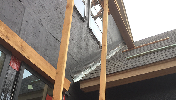
Figure 1: Incorrect flashing behind brick at roof line forces water behind brick wythe and down to sill plate where it then enters the interior at the foundation wall.
Water reaching the top of a basement wall has an opportunity to reach the basement floor for many reasons. The top of the wall is where most shrinkage cracks appear. Even if the basement wall is waterproofed on the exterior, the crack in the top of the wall provides a location for water to migrate down the wall to a form-tie hole leading to the inside of the wall. From there, the water leaks down to the floor.
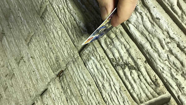
Figure 2 – Common vertical shrinkage crack at form panel joint.
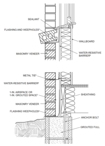
Figure 3: IRC Figure R703.8a depicting proper masonry cladding flashing at window sills and foundations.Exterior Wall Penetrations
Windows, doors, condenser lines, electrical conduit, electrical boxes, plumbing hydrants, poorly installed brick, stone, stucco, siding and even the doorbell are possible locations for water to penetrate the house. Manufacturers of products that risk water penetration provide explicit directions for proper installation of their products. Industry organizations such as the Brick Industry Association, the Engineered Wood Association, the Manufactured Stone Veneer Association and the Masonry Veneer Manufacturers Association, to name a few, also provide installation directions to meet the requirements of the IRC. However, many builders and installing sub-contractors are not familiar with the manufacturer’s directions and simplify the installation of the product. The IRC provides prescriptive requirements covering the penetrations of veneers in case a manufacturer’s installation instructions are not provided.
R609.1 General. This section prescribes performance and construction requirements for exterior windows and doors installed in walls. Windows and doors shall be installed and flashed in accordance with the fenestration manufacturer’s written instructions. Window and door openings shall be flashed in accordance with Section R703.4 (see figures 3 and 4). Written installation instructions shall be provided by the fenestration manufacturer for each window or door.
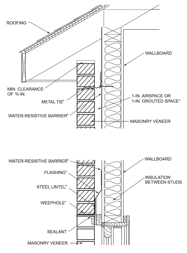
Figure 4: IRC Figure R703.8 depicting proper masonry cladding flashing at window heads and roof.
As a secondary layer of protection from moisture, the IRC requires that a Water-Resistant Barrier (WRB) system be installed on the building between the sheathing and the veneer, regardless of the type of veneer or nature of the penetration. This is available as a liquid application, a roll-out sheet product, or as products pre-applied directly to the sheathing. While each system has manufacturer’s installation requirements, many of these installation instructions are incorrectly followed and thus the systems are incorrectly installed, leading to water infiltration. Incorrectly installed WRB followed by incorrectly installed penetration or veneers can lead to basement water problems.
IRC section 703.4 provides direction on the flashing requirements as:
R703.4 Flashing. Approved corrosion-resistant flashing shall be applied shingle-fashion in a manner to prevent entry of water into the wall cavity or penetration of water to the building structural framing components. Self-adhered membranes used as flashing shall comply with AAMA 711. Fluid-applied membranes used as flashing in exterior walls shall comply with AAMA 714. The flashing shall extend to the surface of the exterior wall finish. Approved corrosion-resistant flashings shall be installed at the following locations:
- Exterior window and door openings
- Intersections of chimneys or other masonry construction…
- Under and at the ends of masonry, wood or metal copings and sills
- Continuously above all projecting wood trim
- Where exterior porches, decks or stairs attach…
- At wall and roof intersections
- At built-in gutters
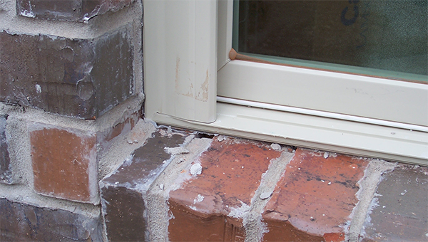
Figure 5: Window installation completed incorrectly leaving gaps for water penetration behind the brick façade.
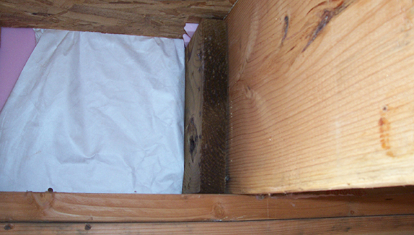
Figure 6: Building wrap installed with joist penetration leaving route for moisture into framed wall past sheathing.
After living in a house for a short period of time, some homeowners decide the builder’s landscaping needs to be improved. A local landscaper is called and a plan is made. They are both proud of their work and protective of the plants to be installed. Raising the beds against the house is often the first decision reached. The results often lead to planting bed dirt-levels that are above the weep holes in the brick, riding up against the siding or stucco, and bringing soil elevations above the top of the foundation wall elevation. Sprinkler systems—often added to keep the ground moist—spray against the house siding, further saturating the soil that has been newly placed above the foundation line and that have a direct line of entry to the basement space under the sill plate.
The IRC requires that exterior grade levels be kept 6 inches below the sill plate and have a slope from the home no less than 6 inches in the first 10 feet away from the foundation. Simply put, maintaining this elevation for the life of the house will help keep water from infiltrating the basement.
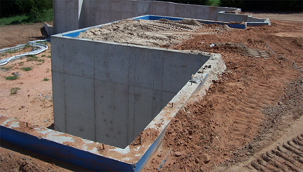
Figure 7: Backfilling of rough grade on this foundation wall is to high leaving no room for final grade.
Waterproofing Systems
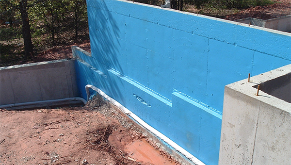
Figure 8: Completed waterproofing spray-on membrane covering entire wall surface from top of wall to footing interface.
Waterproofing the basement walls prior to backfill is a must if the basement is to be kept dry. No waterproof coating or even damp proofing alone can lead to water problems inside the house. The waterproofing products presently on the market are far superior to those used in the past. They may be sprayed, rolled, troweled, put on in sheets and even mechanically fastened. Most waterproofing systems use a combination of polymer and asphalt, several are rubber based, some include plastic compositions, and some even use clay sheets. While it is becoming more common for concrete suppliers to market a crystalline additive to the concrete as waterproofing, be cautious of this application. Tie holes and cracks in walls are not sealed with these products. Their purpose is to prevent water from wicking through the concrete, protect steel reinforcement and stop the formation of capillary channels, which are microscopic paths that allow moisture to move through concrete.
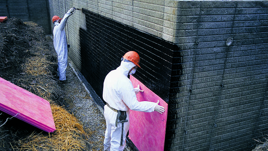
Figure 9: Protection board installation on top of waterproofing application.
Basement Floor Systems
The basement floor is often ignored when considering waterproofing a home or developing a water drainage system, but it can be a main source of water infiltration. IRC section R506 requires a vapor barrier under all concrete slabs-on-ground floors.
R506.2.3 Vapor retarder. A 6-mil (0.006 inch; 152 μm) polyethylene or approved vapor retarder with joints lapped not less than 6 inches (152 mm) shall be placed between the concrete floor slab and the base course or the prepared subgrade where no base course exists.
This has been widely ignored and often incorrectly installed when used. The use of polyethylene sheets under the floor is an acceptable practice. The sheet thickness is important to prevent puncture during installation and placement of concrete as heavy foot-traffic is a reality during the preparation, reinforcement and placement of the concrete. While ACI 302.1R-04 provides a decision chart on when a vapor barrier is to be used and where it is to be placed with respect to the slab, contractors have placed the vapor barrier below sand rather than under the concrete directly. As noted in the IRC section above, in a residential basement, this will lead to the moisture being trapped between the plastic and concrete, forcing the concrete to wick the moisture into the basement living space. The environment for this installation drastically affects the air quality in the house. Plastic placed directly under the floor slab keeps the transmission of unwanted gasses and moisture from permeating the floor of the basement. Concrete contractors often blame concrete cracking on the vapor barrier being placed directly under the floor. In fact, using a lower water-to-cement ratio, with water-reducing concrete additives to increase the slump, will counteract this condition and reduce cracking by reducing the overall shrinkage.
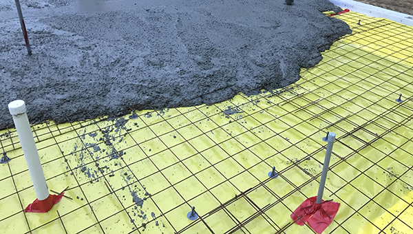
Figure 10: Vapor barrier installed and all penetrations taped prior to placement of concrete for floor slab.
Drainage Systems
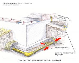
Figure 12: Exterior drainage solution with outlet to interior sump pit per Building America Solution Center at U.S. Department of Energy.
Sub-surface drainage is an important factor in water protection and in reducing hydraulic pressure against a basement wall. Hydraulic pressure is measured in height. The higher the wall the higher the potential hydraulic pressure. Soil type mixed with water also has an impact on hydraulic pressure. The denser the soil and water mixture becomes, the higher the hydraulic pressure will be.
A common method of removing hydraulic pressure is to place perforated pipe—covered with course aggregate and protected with a filter fabric—at the base of the footing and wall. It is often a debate whether to place the drainage pipe below the footing or below the floor. Ideally, placing it lower would help remove more hydraulic pressure. However, placing it on the concrete footing below the floor reduces the chance of hydraulic pressure rising above the floor of the basement and reduces the chance of silting in the pipe. It is important the drain pipe has a location to direct water. A sump pit should be installed inside the building with a pump capable of discharging the input rate of water to a location away from the basement. A common mistake is to take the sump pit discharge to the sewer system. There are several reasons to not connect the two and for starters, the IRC prohibits the connection.
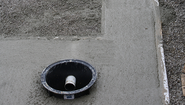
Figure 11: Sump pit installed with cross tubes from footing drainage system.
Residual Wall Moisture vs. Relative Humidity
Humidity in new basements as well as existing basements is often confused as a water leak. Water vapor migrates from a cool environment to a warm one. The interior temperature of a building with habitual space in the basement is normally around 72 F. The temperature gradient on the inside of a basement wall varies with outside ground temperatures when no insulation is against the wall. In the summer, the ground will be warmer at the surface than it is during winter, which will then warm the surface of the inside wall.
The soil temperature will begin to stabilize to a consistent temperature around a depth of 3 feet in most places in the United States. The concrete temperature at 3 feet against the ground is typically about 65 F. This varies throughout the country, but in most cases this is the average ground temperature. An uninsulated basement wall will typically match ground temperature gradients through the height of the wall.
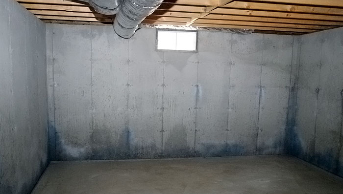
Figure 13: Condensation at uninsulated exterior foundation wall due to thermal gradients and high humidity in the enclosed space.
The moisture in the ground and in the concrete migrates to where it is warmer. This is typically the surface of the concrete, which includes surface cracks. The moisture will not be seen, however, because it evaporates at the surface when the space is conditioned or the air temperature and surface temperature of the concrete are above the dew point. When the humidity reaches a point where the dew point is at or below the concrete temperature, condensation occurs at the surface, including surface cracks. Often the dew point is above the concrete temperature when the basement is a conditioned space.
In homes with an exposed concrete floor in the basement, air flow across the room when there is high humidity will show as lighter areas and there will be damp, dark areas where the air moves slower or not at all in a room. Areas of darkness or surface moisture are typically seen along the lower corners of the basement wall-to-floor interface. Air movement removes the appearance of moisture by evaporating moisture at the surface. Dark concrete in the corners and edges typically indicates high humidity and surface temperatures below the dew point. Waterproofing the basement walls and placing a vapor barrier under the floor are great ideas and are effective at controlling moisture movement but will not reduce air humidity enough to eliminate condensation in most climates. Adding insulation to the exterior of the wall and below the floor with extruded polystyrene will help bring the wall and floor temperatures closer to room temperatures, reducing the appearance of condensation—but the dew point of the air will remain the same. There are several ways to reduce humidity. Conditioning the space through the home’s air conditioning system or a dehumidification system will bring the dew point down by reducing humidity.
The temperature and humidity form energy, like a power plant but at lower levels. Reducing the energy to a value where the temperature is around 72 F and the humidity is around 40 percent will provide a comfortable living space. As the humidity rises and the temperature stays the same, the environment becomes uncomfortable to live in. The longer the humidity stays high the more moisture will accumulate on the basement walls, equipment, and items stored in the basement resulting in that musty smell of mildew.
Therefore, conditioning the space is top priority in resolving the basement climate issue. Perhaps the best method for control is to mix the basement air with the main floor air, which can reduce energy bills and control humidity at the same time. The basement wall and floor temperatures at 65 F provides a great starting temperature for the air conditioning system to work with. By mixing the air of the main floor, which is subject to heat transfer with the exterior temperatures, and the 65 F basement air, a lower energy cost can be achieved. For example: The heat is transferred to the ground from a 72 F room temperature to the 65 F basement walls, the main floor heat is transferred from exterior summer temperatures to a conditioned 72 F interior. Through mixing, a portion of the exterior heat is lost to the basement walls. The movement of air through the cool coil of the air conditioning system removes moisture and does not need as much input energy to reduce the temperature.
Climate Control HVAC vs. Dehumidifier
Instead of spending money on an air conditioner, many contractors place a dehumidification system in the basement to control air quality. When an HVAC contractor chooses to install an oversized air-conditioning unit, one advantage may be that it can still control the humidity level in the basement by running a dehumidifier. However, the disadvantage is that now the homeowner has a unit that runs heating and cooling to control the environment, resulting in higher utility bills in order to keep the space at a constant level of humidity. A dehumidifier accomplishes dehumidification by super cooling the intake air so moisture will condense around the intake coils then heat up the air to discharge back into the room. A fan keeps the air moving across the coils. If this sounds like an air-conditioning system without the heating element, that’s because it is. In most cases a high-quality, variable-speed AC unit will serve the same purpose while circulating more air throughout the house. Dehumidifiers are more effective solutions for removing large amounts of moisture such as when a roof leak or a pipe break brings surface water into the space.
Plumbing Leaks
Plumbing leaks can be a homeowner’s most catastrophic event regardless of the type of foundation. When under pressure, plumbing leaks can wash out the soil under the foundation, causing severe structural damage. Plumbing leaks can flood and damage a basement, the main floor of a house, and even the second and third floors. Hot water lines spray a mist of hot water in the air while creating a whole-house sauna. Drain lines can discharge sewage, filling the basement, the sump pit and the drain tile under the floor with waste—a problem left for those in full body suits to clean up. Those of us in the basement wall business have several recommendations to help builders minimize these problems:
Keep the water supply lines above the footings. Keeping the water lines below frost line while above the footing will help reduce damage to the footers, should a line leak. Backfill the wall and provide as much compaction or support where the water line enters the wall as possible. This keeps the water line from shearing at the wall, should the backfill settle over time. Put a vertical sweep in the line coming into the wall, again helping with shear, should the excavation settle over time. Use a high-quality penetration seal where the line enters the foundation. IRC section P2603.4 requires the pipe through the wall to be placed through a sleeve that is two nominal pipe sizes larger than the pipe, but it does not say what the sleeve should be made of. A Link seal® with an additional coating of sealant on the outside, for those using ridged pipes, will provide a tight seal between the pipe wall and foundation wall. For flexible pipes through the wall, a sealant filling the cavity between the wall and pipe can serve as a sleeve and be watertight. Polyurethane sealants—not expansion foams or silicones—are best for this application. They have little shrinkage and attach to concrete and Pex piping well while maintaining flexibility and toughness for long periods of time. Drain lines made of a UV protective PVC tend to make very stable drain line systems. Keeping the drains from being affected by foundation movement or by soil settlement is also critical. Should a penetration be needed in the wall, make sure a good penetration seal is used between the wall and the pipe.
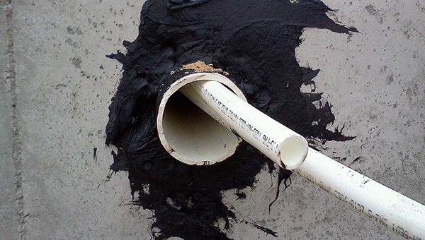
Figure 14: Oversized pipe sleeve protects penetrations in foundation walls from settlement of backfill condition.
A common mistake made to sewer systems is connecting the storm sewer to the sanitary sewer system. Doing so is a code violation and can cause the house to fill with methane gas and cause the drain tile and sump pit to fill with sewage. It can cause the discharge of the storm sewer to pressurize the gravity-fed sewage system, causing line failures, and it can back up the floor drains into the house. Overall, this is a bad idea. Another mistake is to tie the roof gutters into the sump pit discharge or the drain tile. When tied into the discharge, the sump pit pump is required to overcome the head pressure now added to it by the height of the roofline. When tied into the drain tile the sump pump is required to pump roof water along with any water that reaches the base of the wall after draining through the ground. This system is not designed to handle the added work in most cases, so it results in a backed-up system in the basement.
Sump Pump Failures
Until now we assumed the sump pump was always a reliable, working system. Sometimes the sump pump fails from not working all winter, power outages, old age, blown breaker, Faulty GFI, etc. When spring thaws the ground and April showers arrive, we need to make sure the pump is operable. There are several types of pumping systems available today. The electric, motor-driven centrifugal pump is the most common and available pump at most hardware stores or plumbing suppliers. A single pump is often installed but, for safety reasons, an additional pump driven by a battery backup is a good idea. A generator should have the additional pump connected to the generator feed as a critical item. A mechanical siphon (inductor) driven off the water supply can also be used as a backup. Turn the water on and the inductor creates a vacuum in the sump pit with a discharge to the outside.
When a sump pump is installed, make sure a check valve is also installed on the discharge side. A pump without a check valve will allow water in the discharge pipe to return into the sump pit and cycle the pump again. This constant cycling will burn out a pump in a short period of time.
A sump pump is often omitted from a walkout out basement. The belief is that the exterior drain tile will discharge to the exterior at the ends of the walls, and therefore no pump is required. However, neglect to the drainage system can inhibit the ability to discharge water at the same rate water is entering the pipe, causing excessive head pressure on the basement walls. This head pressure may cause water to enter the basement from under the floor. Without interior drain tile or a sump pump, the basement is at risk of water damage.
These are among the top discussion topics at the contractor roundtables I’ve been part of during my time as a foundation contractor and home builder. Paying attention to the critical issues during construction and communicating with the builder are keys to preventing many of these. However, understanding the nature of these common water problems is critical to protecting your interests in new foundation construction; facilitating the right solution and reducing call backs that result in warranty work.
About the Author
Mike is founder and president of Basement Contractors located in Edmond, Oklahoma and a professional engineer. For more than sixteen years he has constructed over 1000 basements in Kansas, Oklahoma and Texas. While others had difficulty in constructing efficient, waterproof basements in Oklahoma, Mike perfected the methods of construction that allow all our customers to enjoy the benefits of basement living. From walk-out to full basements, concrete decks, safe rooms, retaining walls, staircases, or fireplace surrounds, Basement Contractors provides full-service as a concrete construction company. He has been a featured speaker at regional conferences and national conventions including the American Concrete Institute, Concrete Foundations Association and the National Association of Home Builders and their local or state affiliates.
References:
1 2015 International Residential Code® For One- and Two-Family Dwellings published by the International Code Council, Inc., 4051 West Flossmoor Road, Country Club Hills, IL 60478-5795 | Phone 1-888-422-7233 | www.iccsafe.org


The basement floor is one of the main things we first look at!