Concrete Reinforcement Changing
THIS ARTICLE RECOUNTS THE PROCESS CONDUCTED BY ABI CORPORATION, STARTING IN SEPTEMBER 2103, TO INTERNALLY VALIDATE THE MERITS OF USING HELIX MICRO REBAR IN PLACE OF REBAR IN BASEMENT FOUNDATIONS WITH THE GOAL OF REDUCING LABOR.
The requirements to pass the test were simple: the process must save labor and the quality of the finished product must be as good or better than a traditionally reinforced wall. The testing was not scientifically certified and the information in this report is simply a history of the evaluation of the product. It is important this information not be used as a guide or a substitute for the information provided by Helix or a qualified structural engineer.
SMALL SCALE TESTING
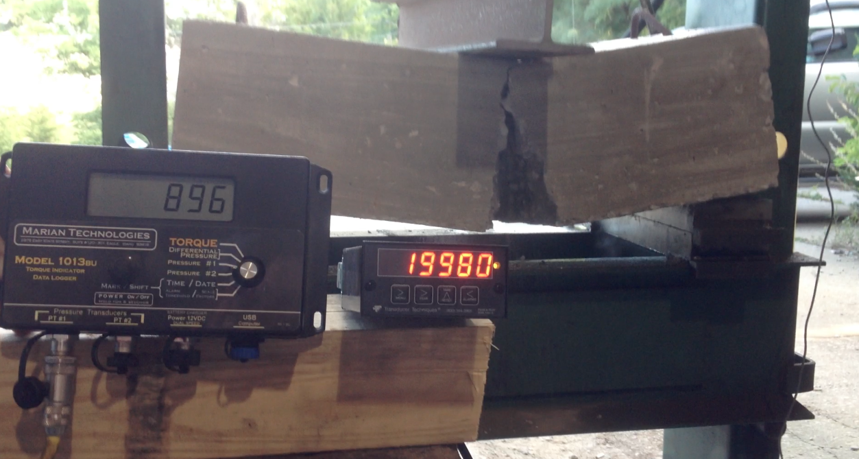
Small scale testing began by casting samples that would be representative of 8” nominal wall sections that measured 26” long by 14” high by 7.5” thick. A 3000lb compressive strength concrete mix was used. After 28 days of curing time, the samples were laid flat in a hydraulic press. Three inches on either side were supported and the rest of the sample spanned approximately 20 inches. Pressure was increasingly applied in the center of the samples until they failed.
SAMPLE A was plain concrete. The sample failed at 19,980 pounds of pressure.
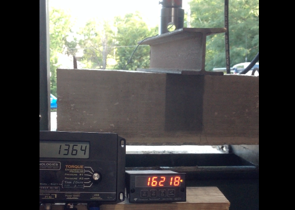
SAMPLE B had one #4 rebar floated into approximately the center or the sample. The concrete failed at 16,218lbs of pressure and the rebar began to yield steadily until 22,018 lbs (~0.5 inch crack width). Then it dramatically lost its ability to carry load and the crack quickly opened ~2 inches.
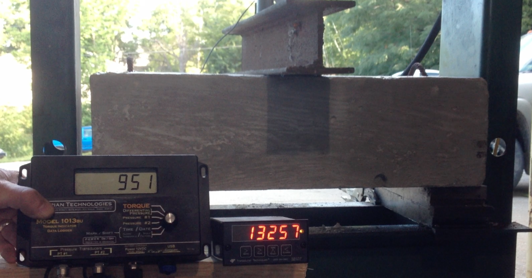
SAMPLE C had two #4 rebar floated into approximately the center. An audible pop was noted at 13257lbs when the concrete failed on the tensile (bottom) side of the sample and a visible crack began to form.
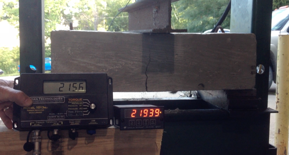
Complete cross sectional failure of the concrete occurred at 21,939lbs and the rebar quickly began to yield to the pressure. The yielding #4 bars were able to maintain a load reading of about 14,000lbs until the crack width opened to approximately 0.05 inches.
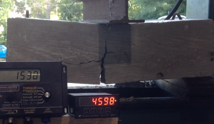
At that point a metallic snapping sound was noted and the pressure gauge dropped to 4598lbs and the crack started to open must faster.
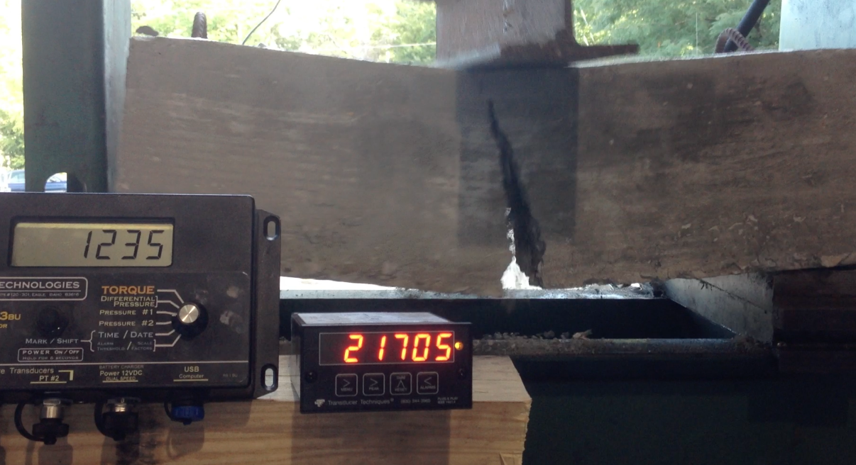
SAMPLE D had 9lbs/yard of Helix 5-25. No rebar was used. Under rapid loading the sample failed at 21,705 lbs of pressure.
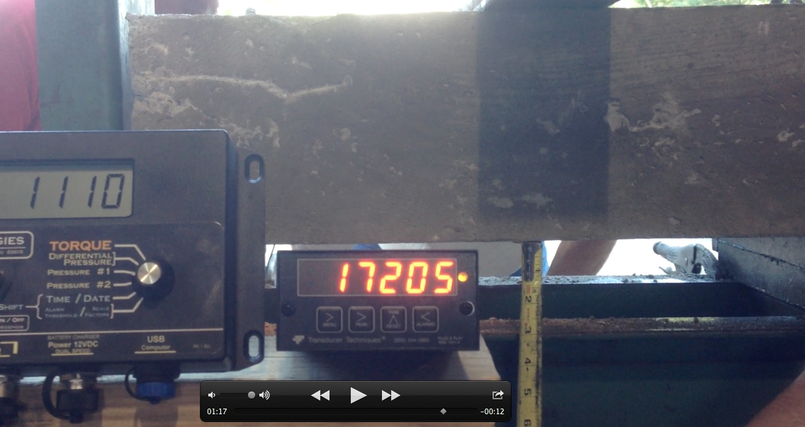
SAMPLE E had 9lbs/yard of Helix 5-25. No rebar was used. The load was applied much slower than sample 3 to try and detect the yielding of the Helix.
The sample failed at 17,205 lbs of pressure.
Dan Bromely the President of ABI Corporation said, “This test convinced me to move forward with the wall.” The wall he was referring to was a full-scale basement foundation section he poured behind the corporate headquarters located in the South East suburbs of Kansas City, Missouri.
THE FULL SCALE TEST WALL
The materials for the test started as 3000 psi compressive strength mix with 9lbs per yard of Helix 5-25 added at the batch plant. Water was added on site to achieve a 9 inch slump resulting in an unknown, but certainly much lower compressive strength. Aluminum Forms were then used to cast an 8 inch nominal wall, 9 foot tall, 16 foot long with 90 degree turn sections at each end. Other than corner steel, no traditional rebar was used in the wall, only Helix twisted steel micro reinforcement.
The wall was poured and the formwork was removed after 18 hours. It was immediately evident that an 8” long vertical shrinkage crack formed starting at the embedment of an anchor bolt and running down the wall. ABI experts were certain the shrinkage crack was the result of the high ambient temperature and the water added to the concrete mix at the site. This type of crack would have formed in the plastic phase of the concrete no matter what reinforcement was used.
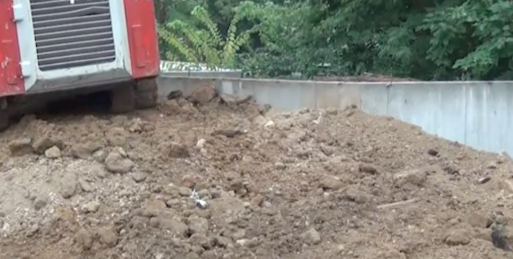
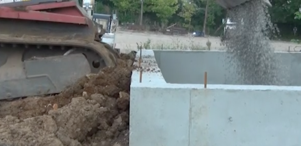
The wall was allowed to cure 7 days and then backfill was placed against the wall. The method of backfill is important because the 12,000-pound loader was run parallel and close to the wall to add additional dynamic and static compressive loads to the wall. Ultimately, 100% unbalanced backfill was achieved with no evidence of change in the wall (see image below).
A hose was placed on the backfill near the wall and water was allowed to saturate the backfill for 7 days. Not only did the backfill become saturated, the soil at any point within 15 feet of the test wall was saturated to a depth of about 8 inches. Again, there was no obvious indication of change in the wall.
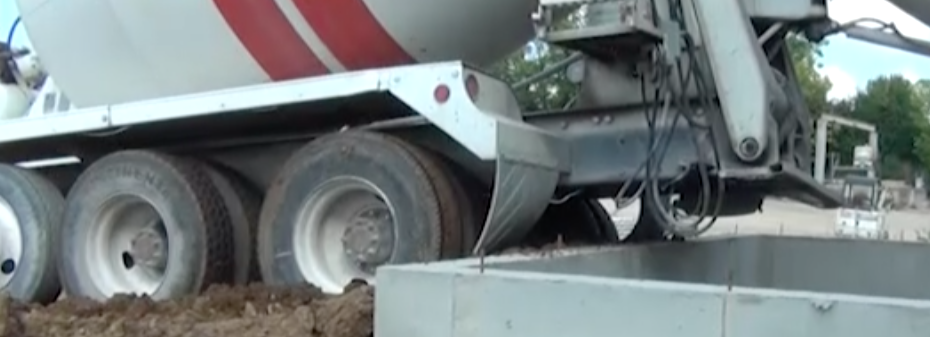
The next phase of the test likely generated the most severe loading of the wall. After allowing the backfill to dry, a ready mix truck with 10 yards of water and gravel, weighing approximately 70,000 pounds was backed up to the wall to simulate the pouring of a basement floor. In addition to the weight of the truck, the rear tires of the ready mix truck were spun against a compressed layer of approximately 10 inches of backfill that was trapped between the tires and the wall. Once the truck was stopped, the drum was rotated at high speed and abruptly stopped and rotated in the opposite direction several times. The shifting material and changes in drum direction caused the truck to heave back and forth transferring unknown amounts of energy to the soil inches from the wall. Neither the heaving of the truck nor the simultaneously applied weight and the pushing force of the tires created a visible change in the wall (see image below).
The final active phase of the test was backfilling gravel over the wall with the same 12,000 lb. loader used earlier in the test. The loader with full buckets of gravel was driven up to the wall such that the tracks pushed against and climbed on top of the wall (see image below)
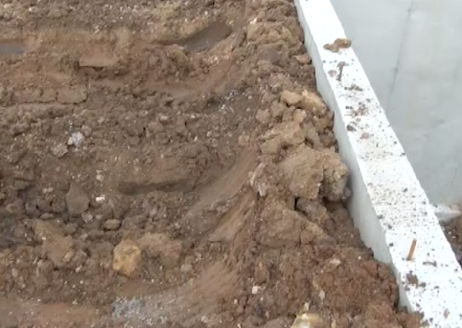
The wall section is now 7 months old and has gone through the 2013-14 winter. The foundation on what would normally be the interior of the basement has been completely exposed since it was poured. There is no doubt the ground froze under the footing so an unknown amount of force was applied to the wall from frost heave. The original 8 inch long shrinkage crack has grown to a 48 inch long tight, but visible crack. During an inspection of the wall on March 18th, 2014 Dan Bromley commented,“That’s nothing” while observing the hairline crack indicating there it was nothing to be concerned about with regard to the integrity of the wall (see image below).
MARKETING STRATEGY
After seeing the results of the in-house testing, ABI was convinced they could offer better quality foundations by using Helix. The next step was to develop a marketing strategy and present the idea to their builders. Like most good marketing strategies, the ABI message is easy to understand and highlights the advantages of the product. Below are the ABI reasons to promote Helix:
- After extensive research and in-house testing we feel that it improves the quality of our foundations.
- It will help us be more productive. We can do more with less people and will help us mitigate the effects of the housing labor shortage as this market grows.
- Safer
- As a builder there may be a marketing opportunity to homebuyers; a chance to promote a better foundation product with the synergistic combination of waterproofing on a Helix reinforced wall.
DOSING HELIX
There are several important considerations when planning how to place Helix into the ready mix truck. Helix comes in 45lb boxes. To achieve a 9lb per yard concentration in a 10 yard truck two boxes (90 pounds) have to be added to the truck. Using the example of a basement that requires 60 yards of concrete, it would require six trucks of concrete and a dozen 45-pound boxes. In order to get the material into the truck, two important tasks have to be accomplished. The first is lifting the Helix to the level of the hopper and the second is a sifting the material so that no clumps are introduced into the truck.
ABI adds Helix at the concrete plant where the material can be lifted to an elevated platform with a forklift. Once the boxes are on the platform, one worker to stand safely with the hopper at waist level and sift the material into the trucks. As the number of projects using Helix increases they intend to look at automated dosing equipment.
Field dosing is an option as well, but can be physically challenging. To experience the worst-case scenario, Dan Bromley personally climbed the truck and sifted the material through a manual doser. Climbing a rear discharge truck without adequate truck mounted work platforms is the least desirable method. It is physically taxing and has a moderate safety risk for the worker. Front discharge trucks with safe working platforms provide for a better situation, but the material still has to be lifted to the level of the platform.
Methods of getting the helix into the truck are really only limited by ones imagination and mechanical ability as evidenced by the videos posted online. Do to an apparent lack of availability or unreasonably high cost, most dosing devices have been self- built by the companies that use Helix. Some are vibrating hoppers with blowers, some are vibrating table with chutes. One off-the-shelf solution may a fiber conveyor like the one available from Portable Conveyors (800) 456-7687. But the conveyor below still lacks a vibratory screen or tray to sift the material before it goes into the hopper and it is more expensive than a most of the homemade solutions.
PRODUCT ACCEPTANCE
In order to gain the support needed for technical acceptance in the Kansas City, Metropolitan Area, ABI thought is was important to have the involvement of well- known residential engineer. Therefore, they contracted Apex Engineering to prepare
drawings with Helix as an alternative to traditional rebar. Last fall, Luke Pinkerton, the President and Chief Technology officer for Helix was in town for a presentation at Kewitt and he was able to come to ABI and meet with Dan Bromley and Clayton Hess of Apex engineering. After that initial meeting, Apex did an extensive review of the science behind Helix.
Apex engineering was able to review a complete engineering report prepared by Helix based on a set of plans for a typical Kansas City foundation design. They were also able to review the documentation on the testing done to prove Helix’s ability to serve as a structural concrete reinforcement. The bulk of that information is now available in a single report named the ER-0279 Report.
Once satisfied, they prepared sealed drawings with notes for the use of Helix as an alternative. Unfortunately, the process took more than 2 months.
In Helix’s 12 years on the market it has been mostly confined to large commercial projects. Those projects are mostly engineered projects inspected by the engineers who designed them and the responsibility remains with the engineer. City inspectors however normally inspect residential construction and they rely on city codes that vary from city to city. The ER-0279 report doesn’t require an inspection to be conducted when using Helix. It only requires that the dosage be annotated on the batch ticket and that a written copy of the batching procedures to be on
hand when Helix is added to concrete. Since there isn’t anything to inspect other than the batch ticket annotation and the presence of written dosing procedures, it will likely present some city building departments with an unknown situation. The ER 279 report does however provide information about verification of dosage. Anyone who wants to make sure the correct amount of Helix is in the mix can take sample amounts of plastic concrete and wash away the cement, separate the Helix, from the aggregates and weigh it.