Tech Talk: Footing Discontinuities According to Code
As Published by Concrete Homes Magazine (May-2006)
by James Baty, CFA
Editor’s Note: As part of our partnership with the Concrete Foundations Association (CFA), the following article is the second in a series on residential construction codes. For more information, visit cfawalls.org or call (319) 895-6940.
Codes are developed to provide assurance that structures are designed and constructed to withstand the test of time, not only for life safety but also for long-term durability. Yet codes can also be so complex that implementation causes struggles that delay, or worse yet, halt work. Residential construction is no different than any other construction market today. Recognizing this, the American Concrete Institute created a committee specific to the residential industry (332-Residential Concrete) to create guides and standards that help shape the quality and efficiency of this market. Nearly 20 years after the formation of this committee, the first ACI Residential Concrete Code has been published. Over the coming months, this article will digest some of the more substantive areas altering or improving the requirements for residential concrete as the industry prepares to shift from design and construction by ACI 318, chapter 22 to ACI 332.
The ACI 332 Standard, developed by this committee, provides the minimum cast-in-place design and construction requirements for one- and two-family dwellings and their accessory structures. The current version of the code (332-04) specifically addresses those requirements for concrete footings (wall, thickened slab and isolated), basement or foundation walls constructed only with removable forms and slabs-on-ground. Other elements and methods for residential construction do exist but are beyond the scope of this current document. Those not included remain under the provisions of ACI 318 and other code references.
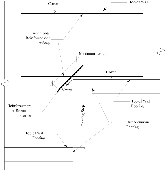
Figure 1 – Foundation wall spanning the horizontal discontinuity in the footing
There are many aspects of current construction that all too often are not easily supported or referenced in a general building code. One example is the design of footings and foundations at extreme changes in elevation, such as the step from a basement foundation to a garage wall. This design requirement also exists where a building lot falls rapidly from front to back, requiring the foundation wall to step at varying intervals. Still other conditions exist where the design must account for footings spanning trenches or poor soil conditions. ACI 332 has developed guidelines for these conditions, supporting the current practices that are followed in the field with sound design guidelines.
Designing for footing discontinuity
Fundamentally, the footings transition the load from the house and the foundation walls to the sub-grade. The foundation walls provide the vertical transfer and support the lateral pressure applied by the earth. However, where significant changes in elevation occur, an area exists in the excavation where a continuous footing is not practical or effective. This transition is considered a discontinuity in the footing design and the foundation wall must be engineered to perform as a beam spanning from the end of the footing above to the beginning of the footing below. ACI 332 states:
Where a wall footing is discontinuous due to an abrupt elevation change, the maximum horizontal discontinuity of the wall footing shall be 4 feet.
The code recognizes that there are areas requiring abrupt elevation changes in the foundation. Referred to as steps, these areas are typically experienced in walk-out basements, at significant changes in the grade, and in the transitions to garage foundations. An example of this condition is seen in Figure 1.
The condition created by a footing discontinuity is limited in ACI 332 to a maximum dimension for the discontinuity (distance between the footing ends) of 4 feet. This condition also requires the following:
At discontinuous wall footings, where wall footing elevation change is greater than twice the footing thickness, place a minimum of two No. 4 horizontal reinforcing bars, one at the top and the other at the bottom of the wall, in addition to other required wall reinforcement. These bars shall extend at each end at least 36 inches into the wall portion supported directly by the top and bottom wall footings. The bars shall be placed in the middle third of the wall thickness.

Figure 2: Footing jump formed with aluminum wall panel forms before bulkheads are installed.
By providing the reinforcement as stated above, the foundation wall spanning the footing discontinuity transfers the vertical load within that span to the areas of the wall directly over the two footing sections as a structural beam. The footings then transfer the combined loads to the sub-grade.
Designing for unsupported footing conditions
There are also conditions encountered from time to time on jobsites where the footing must span a trench or a soil condition that is less stable than the rest of the sub-grade. ACI 332 addresses these conditions with a variety of requirements. An unsupported footing is considered any distance where the load transfer of the footing cannot be maintained at the same pressure condition of the assumed sub-grade. These are most commonly found around water or sanitary pipes, power trenches or areas where poor soil compaction settles below the surface of the surrounding sub-grade. In general, good practice suggests that any backfill should be compacted by tamping to the level of the bottom surface of the footings and the top level of the surrounding sub-grade. This will obtain adequate bearing and minimize the likelihood of detrimental settlement.
However, there are conditions where this is not appropriate or possible. For these conditions, the footing must be considered a structural beam and designed to span the sub-grade condition. ACI 332 requires that:
Where an unsupported wall footing section does not exceed a 3-foot span, a minimum of two No. 4 reinforcement bars shall be placed in the bottom of the footing and extend at least 18 inches into the supported sections on both sides. Reinforcement bars shall have a minimum cover of 3 inches from the sides and bottom of the footing.
In other words, reinforcement (or additional reinforcement) is added to the footing at this condition. It must extend a minimum of 18 inches beyond the edge of the points where the sub-grade is considered to be insufficient for continuous support equal to that of the prepared sub-grade. Also, it is important to note that this design can only be used for a maximum span of 3 feet. Beyond this distance, the affected sub-grade must be engineered to the condition surrounding it.
Finally, ACI 332 provides that for areas where the soil under the intended footing has been removed by trenching or other methods, the void must be backfilled. Although it may not have to be compacted as stated above, the backfilling is important to prevent the adjacent sides of the trench or opening from becoming more unstable, extending the distance of the unsupported condition.
Together in ACI 332, design professionals and industry experts have combined efforts to improve the rationalization and the construction of residential footings in response to the market growth and constant pursuit of the mantra “bigger, better, faster and more economy.”
Contact Jim Baty, Technical Director, (319) 895-6940 or jbaty@cfawalls.org